


P A G E 20
E a s y M x
P R O
v 7 a
U s e r M a n u a l
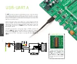
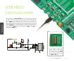
USB-UART A
Enabling USB-UART A
The
UART
(universal asynchronous receiver/trans mitter) is one of the most common
ways of exchanging data between the MCU and peripheral components. It is a serial
protocol with separate transmit and receive lines, and can be used for full-duplex
communication. Both sides must be initialized with the same baud rate, otherwise the
data will not be received correctly.
Modern PC computers, laptops and notebooks are no longer equipped with RS-232
connectors and UART controllers. They are nowadays replaced with USB connectors and
USB controllers. Still, certain technology enables UART communication to be done via
USB connection. Controllers such as
FT232RL
from FTDI® convert UART signals to the
appropriate USB standard.
USB-UART A communication is being done through a FT232RL controller, USB
connector
(CN22)
, and microcontroller UART module. To establish this connection,
you must connect
RX
and
TX
lines of the microcontroller to the appropriate input and
output pins of the FT232RL. This selection is done using DIP switches
SW12.1
and
SW12.2
.
1
2
3
4
5
6
7
8
9
10
11
12
13
14
15
16
17
18
19
20
21
22
23
24
25
26
27
28
TXD
DTR#
RTS#
VCCIO
RXD
RI#
GND
NC
DSR#
DCD#
CTS#
CBUS4
CBUS2
CBUS3
CBUS0
CBUS1
OSCO
OSCI
TEST
AGND
NC
GND
GND
VCC
RESET#
3V3OUT
USBDM
USBDP
FT232RL
U2
FT232RL
VCC-3.3V
VCC-5V
C11
100nF
LD69
LD70
RX-LED1
TX-LED1
R15
4K7
R14
2K2
VCC-3.3V VCC-3.3V
R18
4K7
R21
10K
FTDI1-D_N
FTDI1-D_P
RX
TX
D
AT
A BUS
1
2
3
4
5
6
7
8
O
N
SW12
TX-FTDI1
RX-FTDI1
PA9
PA10
SH
IE
LD
0
GND
B1A12
VBUS
B4A9
CC2
B5
DP2
B6
DN2
B7
SBU2
B8
SBU1
A8
DN1
A7
DP1
A6
GND
A1B12
VBUS
A4B9
CC1
A5
CN22
USB TYPE-C
D-
D+
R82
5.1k
R83
5.1k
R84 27
R85 27
USB-VBUS
1
2
3
5
4
6
I/O1
GND
I/O2
I/O2
VBUS
I/O1
D8
USBLC6-2P6
D-
D+
D-
D+
USB-VBUS
GND
In order to enable USB-UART A
communication, you must push
SW12.1
(PA9) and
SW12.2
(PA10)
to
ON
position. This connects the
TX
and
RX
lines to
PA9
and
PA10
microcontroller pins and its UART
module.
COMMUNICA
TION


