


18
Mains error
The mains error indicator is illuminated if the mains
voltage is too high or low. The indicator remains
illuminated 5 seconds after the mains error is
corrected/removed.
Welding process
This display is used to select
the welding process, e.g. MMA electrode or TIG. The
function is fixed during welding, and shift from TIG to
MMA is not possible before the post-flow has been
finished.
MMA electrode
MMA electrode welding has been selected.
TIG
TIG welding has been selected.
Function of the torch trigger
(The trigger method)
This display is used to decide whether the start/stop
method of the TIG welding process is to be two-
times, four-times (latching), or spot. Welding
process means the phases: pre-flow, slope-up,
welding with adjusted current, if necessary, reduced
current, slope-down and post-flow. It is not possible
to change trigger method during the welding process.
Two-times
The welding process begins by pressing the torch
trigger. Welding continues until the trigger is re-
leased again which effects the slope-down period.
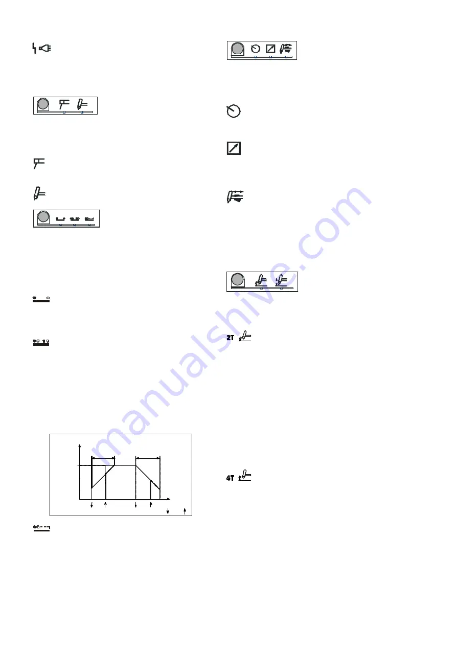
Four-times
The welding process begins by pressing the torch
trigger. Releasing the torch trigger during gas pre-
flow activates the slope-up period. If the torch trigger
is released during the slope-up period welding con-
tinues with the adjusted welding current. In order to
stop the welding process the trigger must be
pressed again after which the slope-down period
begins. The slope-down period can be stopped by re-
leasing the trigger.
Set welding
current
slope-up
slope-down
trig down ( ) / up ( )
time
Amp
Spot
The welding process begins by pressing the torch
trigger. Welding stops automatically, depending on
the time set in spot time.
Amp setting function
The AMP keypad is used to
select the method by which the required welding
current shall be established. This welding current is
then shown in the display and cannot be changed
during the welding process.
Internal adjustment
The control knob positioned below the digital
display is used to set the current.
External adjustment
Current setting to be by means of a Migatronic
remote control unit. The remote control unit is
connected to a plug positioned on the rear of the
machine (not standard equipment).
Torch adjustment
Current setting to be by means of the current
control knob located in the handle of a Migatronic
dialog torch, if a dialog torch is used. The maximum
current is set with the control knob on the front
panel. The torch control is used to reduce the current
from the maximum set current to the minimum
current.
Ignition of TIG welding
It is possible to choose be-
tween two different methods
of ignition for TIG welding: High-frequency (HF) and
LIFTIG ignition. The method of ignition cannot be
changed during the welding process.
Two-stroke
This symbol means contact-free striking.
The arc is established in the following way:
1) The torch is placed so that the Tungsten elec-
trode is quite close to the welding spot (1 or 2
mm).
2) The torch trigger is activated, and the high voltage
generator of the machine will produce a voltage
impulse that ignites the arc. The welding process
has started. The welding process will stop when
the torch trigger is deactivated. The arc will
extinguish after the period of slope-down time.
The torch is held at the welding spot until after
the period of gas post-flow time in order to protect
the welding spot against oxidation.
Four-stroke
This symbol means contact-free striking.
The arc is established in the following way:
1) The torch is placed so that the Tungsten elec-
trode is quite close to the welding spot (1 or 2
mm).
2) The torch trigger is activated, and the high voltage
generator of the machine will produce a voltage
impulse that ignites the arc. The torch trigger is
deactivated. The welding process will stop when
the torch trigger is reactivated. The arc will
extinguish after the period of slope-down time.
The torch is held at the welding spot until after
the period of gas post-flow time in order to protect
the welding spot against oxidation.
Содержание PILOT 1800
Страница 73: ...73 PILOT 1800 2400...
Страница 74: ...74 WATER COOLING UNIT PILOT 1800 2400...
Страница 76: ...76...
Страница 82: ...82 PILOT 1800 2400 VANDK LEMODUL WATER COOLING UNIT WASSERMODUL MODULE HYDRAULIQUE...
Страница 84: ...84...
Страница 85: ......


