background image


CropHawk Draper Platform Operators Manual                                                                                                                        33 

Removable Components 

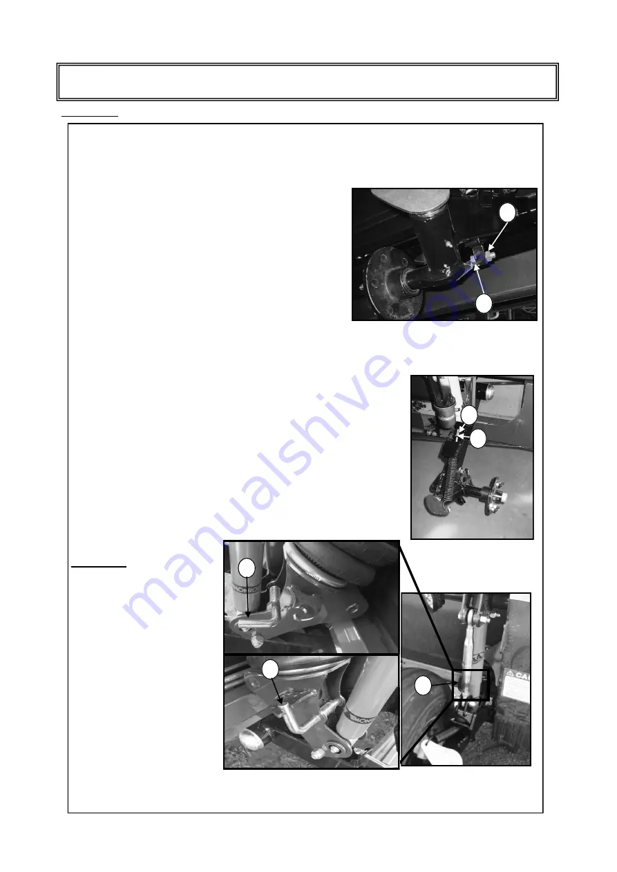
Ground wheel alignment 

Ground wheel camber and alignment is changed by the adjustment of the ground wheel stop bolt (A) .  

1. 

Loosen lock nut (B). 

2. 

Wind bolt (A) in clockwise direction to change alignment of 
the front side of the tyre to tow into the centre of the plat-
form and to roll the top side of tyre to the centre of the plat-
form. Wind bolt (A) out anti-clock wise to change alignment 
of the front side of the tyre to tow to the outside of the plat-
form and to roll  the top side of the tyre to the outside of the 
platform. 

3. 

Tighten lock nut (B). 


Ground wheel caster return Spring Adjustment 

Ground wheel castor springs can be adjusted to ensure ground wheels return to 
parallel when they are lifted above ground height. To adjust more tension on the 
springs follow steps below. 

1. 

Loosen lock nut (A). 

2. 

Tighten nut (B) until spring holds the weight of the wheel against the 
ground wheel stop. 

3. 

Tighten nut (A). 

NOTE: over tensioning of the spring can damage the spring. Spring   tension 
should be set to just carry the weight of the wheel against the stop. 

Ground Wheel Transport Lock 

IMPORTANT: Ensure platform is 
fully lowered on the ground or 
airbags are deflated and there is 
no tension on ground wheel 
transport lock pin 

(A) 

before re-

leasing, as pressurised release 
of wheel  arm can cause serious  
Injury or death. 

1. 

Lower platform to ground 

2. 

Engage (B) / Disengage (C) 
lock pin (A) 

NOTE: Ensure ground wheel lock is 
engaged when transporting as con-
tact with the road  surface will dam-
age ground wheel components. 

NOTE: for purpose of this description, 
ground wheel has been removed. 

Adjustments 

Содержание Crophawk Draper Platform

Страница 1: ...ors Manual 1 OPERATOR S MANUAL From Serial Number MWF 11040656 MIDWEST CROPHAWK DRAPER PLATFORM 2012 Edition A MidWest Fabrication Pty Ltd 6 Irvingdale Road Dalby Qld Australia 4405 P 07 46622137 F 07 46622138 service midwest net au ...

Страница 2: ...ery manual have been completed and returned to Mid West Fabrication Purchase Information Fax Email Online Freight Delivery Report Fax Email Online Pre Delivery Report Fax Email Online Customer Installation Form Online Only Serial number Signed MWF Dealership Representative Platforms not registered for warranty may be ineligible for warranty and manufacturer product improvement programs ...

Страница 3: ...fore not subject to manufacturer s warranty Drive Belts All belts are adjusted in the factory checked and adjusted on pre delivery If the belt is proven faulty a claim will be considered If the claim involves belt slippage or miss alignment claim will be rejected Reel Pick up reel fingers and bats are crop engagement parts and therefore not subject to manufacturer s warranty Reel bush wear is gove...

Страница 4: ...k Draper Platform Operators Manual Serial Number Information Modification Upgrade Record PURCHASE INFORMATION Dealers Name Address Phone Purchase Date Model Serial Number Delivery Date Date Modification Upgrade ...

Страница 5: ...ome familiar with recommended procedures before attempting to unload assemble or operate the Midwest Crophawk Draper Platform Record of Model and Serial numbers should be kept in a secure place off the platform These numbers may be required should the platform be stolen or when ordering parts through your MidWest dealer This Operators Manual should be considered a permanent part of the MidWest Dra...

Страница 6: ... 22 Claas initial Platform setup 24 John Deere initial Platform setup 26 Removable Components 30 Reel 35 Feed Drum 41 Drive System 45 Knife Cutterbar 54 Adaptor 56 Draper Belts 59 Hydraulic Electric system 65 Harvesting Tips 68 Connecting and Disconnecting the Draper 69 Storage Procedures 71 Lubrication General Maintenance 73 Unloading the Platform 78 Platform Restraint Guidelines 81 Trouble Shoot...

Страница 7: ...arn how to operate the draper platform and how to use it properly Under no condition should anyone operate the draper without proper instruction If you do not understand any part of this manual contact your Dealer Safety Decals Throughout this manual and on draper decals you will find precautionary statement followed by specific instructions These precaution are intended for you personal safety an...

Страница 8: ...8 CropHawk Draper Platform Operators Manual Continued on next page Safety ...

Страница 9: ... stopped before making any adjustments or servicing on the platform Never leave combine unattended while engine is running Be sure to remove ignition key and lock the operators cab Stay Clear of Draper Platform Platform knife PTO shafts draper belts reel and drives cannot be completely shielded due to their function Stay clear of these moving components during operation Always disengage combine se...

Страница 10: ...e Hydraulic System Caution Hydraulic oil is a flammable liquid Never attempt to gas heat or weld any hydraulic components lines or oil reservoirs To do so may cause an explosion causing serious injury or death Repairs of this nature should be carried out by a qualified tradesperson only Remove Crop Debris Remove crop debris from moving parts as this is a fire hazard Check and clean these areas fre...

Страница 11: ... parts that could be dislodged or damaged during transport Check all wheel nuts on transporter and hitch are tight Ensure platform ground wheels are locked in the transport position Check hydraulic coupling hoses are secure and PTO shafts are locked in transport position to ensure they will not pinch or drag during transport Safety chains must be securely fastened to the header or transporting veh...

Страница 12: ...e are recommended 2 Removable Components This sections relates to all components that can be removed from the frame as a sub assembly or individual item that are not recognised in a specific platform area and include the following components 1 Ground wheel Assembly Tyre removed for clarity 2 Nose cone crop divider 3 Crop throat area 4 Sand Trap 5 Covers 1 Frame 2 Removable Components 3 Reel 4 Feed...

Страница 13: ...tractable fingers with 150 mm 5 9 in of travel and is protected by a bi directional torque clutch accommodating combine feed er reverse The Drum has 70 mm 2 7in of vertical travel and can be adjusted 60 mm 2 3 in fore and aft 5 Drive system The MidWest platform drive system relates to all mechani cal driven components Power input is from the combine s feeder house output shaft via a PTO shaft to t...

Страница 14: ... platform to the feeder housing of the combine and is unique to the model and series of combine The adaptor comprises two separate floatation systems for both vertical and lateral movement The vertical float system is suspended by 2 air bags linked via a tank enabling 100mm vertical travel with the ride being controlled by adjustments to air bag pressure The lateral floatation system supports the ...

Страница 15: ... idler roller 9 Hydraulics Electrics The MidWest platform contains two separate hydraulic systems 1 The self contained fully integrated hydraulic system drives the draper belts The feeder house drive shaft from the combine is connected to an input drive shaft on the platform via a PTO shaft The accelerator gearbox is mounted on the input shaft and drives the hydraulic pump The draper con trol circ...

Страница 16: ...m 15461mm B Actual Cutting width including nose cones 11204mm 12575mm 12880mm 13462mm 15166mm C Knife cutting width 11049mm 12420mm 12725mm 13487mm 15011mm D Ground wheel Tracking Width 7712mm 9083mm 9837mm 10600mm 12125mm E Transport Width Tyres Nosecones Removed 2425mm 2425mm 2425mm 2425mm 2425mm F Transport Width Tyres Nosecones Fitted 2713mm 2713mm 2713mm 2713mm 2713mm ...

Страница 17: ...pm 15 faster then outer belts Speed Control Outer Hydraulic adjustable in cab control option Centre Hydraulic adjustable Drive Rollers vulcanised rubber on outer draper belts steel on centre feed belt Feed Drum Diameter 406 4 mm 16 diameter Feed drum fingers 19mm diameter Number of fingers 18 Finger reach 150 mm Operating speed 210 240 rpm 25 ft 27 ft 30 ft 33 ft 36 ft 41 ft 42 ft 45 ft 50 ft Reel...

Страница 18: ... and sickle has 76 mm 3 centres NOTE Rated to 11 kph cutting speed No Choke Guards Cereal Pulse crops No choke long short guards are used with standard sickle knife sections 76 mm 3 centres design gives open access to sickle while half guard helps reduce crop shatter in pulse crops P4 Guards Cereal and light crop P4 guards 4 finger used with standard sickle sections 76 mm 3 centres Ideal for highe...

Страница 19: ...s manual see LUBRICATION section in this manual When using locking element increase torque values by 5 Bolt dia A Bolt Torque SAE 5 SAE 8 N m lb ft N m lb ft 1 4 12 9 15 11 5 16 24 18 34 25 3 8 43 32 56 41 7 16 68 50 95 70 1 2 102 75 142 105 9 16 149 110 202 149 5 8 203 150 271 200 3 4 359 265 495 365 7 8 569 420 813 600 1 867 640 1205 890 A SAE 5 SAE 8 Bolt Torque Bolt dia A 8 8 10 9 N m lb ft N ...

Страница 20: ... to second hand combines Adjust bottom adapter link A to 640mm from centre to centre of link pins see diagram NOTE Step 3 is to obtain maximum clearance for initial set up only and NOT for operating the platform Check that feed drum is in full forward position see FEED DRUM ADJUST MENTS in the operators MANUAL Drive combine slowly for ward until feeder house is centered in platform adapt er openin...

Страница 21: ...sengage combine safety stop and on level ground lower platform until skid plate lightly touches the ground Shut off engine set park brake and remove key Level platform see LEVEL PLATFORM in ADAPTER ADJUSTMENTS section in this manual Set platform pitch see PLATFORM PITCH in ADAPTER ADJUSTMENTS section in this manual Test reel lift circuit and phase cylinders see HYDRAULIC ELECTRIC ADJUSTMENT sectio...

Страница 22: ...l ties arising IMPORTANT For Combine preparation see combine harvester s operators manual Set combine feeder house face to position 4 5 refer to com bine operator s manual Remove feeder house shroud A lifting lug B and angle or nylon strips C from feeder house Check feeder house chain slate protrusion past feeder house face If greater than 50mm 2in remove link out of feeder chain more relevant whe...

Страница 23: ...ng surfaces are clean Before proceeding ensure that platform is securely mounted to the combine Disengage combine safety stop and on level ground lower platform until skid plate lightly touches the ground Shut off engine set park brake and remove key Test reel lift circuit and phase cylinders see HYDRALIC ELECTRICS ADJUSTMENT section in the operators manual Test light function fore and aft hydraul...

Страница 24: ... relevant when fitting to second hand combines Adjust top pivot ball slide plate to its most forward position adaptor moves away from feed drum Adjust bottom adaptor link to max clear ance 640mm from centre to centre of link pins see diagram NOTE Adaptor distance is to obtain maximum clearance for initial set up only and NOT for operating the platform Check that feed drum is in rear mount posi tio...

Страница 25: ... circuit and phase cylinders see HYDRALIC ELECTRICS ADJUSTMENT section in the operators man ual Test light function fore and aft hydraulic circuit and phase cylinders see HYDRAULIC ELECTRIC ADJUSTMENT section in this manual Set minimum reel height see LEVELING REEL MINIMUM REEL HEIGHT in REEL ADUJST MENTS section in the operators manual Run platform at idle for 2 3 minutes set parking brake shut o...

Страница 26: ...pter link A to 640mm from centre to centre of link pins see diagram NOTE Adaptor distance is to obtain maximum clearance for initial set up only and NOT for operating the platform Check that feed drum is in full forward position see FEED DRUM ADJUSTMENTS in the operators MANUAL Drive combine slowly forward until feeder house is centered in platform adapter opening Raise feeder house until top of f...

Страница 27: ...ITCH in ADAPTER ADJUSTMENTS section in the operators manual Test reel lift circuit and phase cylinders see HYDRALIC ELECTRICS ADJUSTMENT section in the operators manu al Test light function fore and aft hydraulic circuit and phase cylinders see HYDRAULIC ELECTRIC ADJUSTMENT section in this manual Set minimum reel height see LEVELING REEL MINIMUM REEL HEIGHT in REEL ADUJST MENTS section in the oper...

Страница 28: ... Check oil reservoir level and inspect hydraulic system for leaks Maintain oil level within the sight glass located on the oil tank on the rear right hand side of the platform see image 1 Inspect the Outer Draper belt tracking ensuring the centre rib on the Outer Draper belts are aligned in the drive and idler roller grooves see image 2 Inspect the centre belt tracking ensuring the side rib on the...

Страница 29: ...djust if necessary the following ITEM RANGE ACTUAL FEED DRUM PULLEY 210 240 RPM KNIFE DRIVE PULLEY 640 690 RPM OUTER DRAPER ROLLER 650 750 RPM 5 Check Knife for any extreme rub marks or hot spots caused by excessive friction adjust as required 6 Run Platform up to full speed IMPORTANT Extreme care and safety measures must be used at all times as the following proce dure is undertaken while Platfor...

Страница 30: ...5 Retighten 7 x bolts A B NOTE Bolts that retain the sand trap also retain the crop throat floor sheet and under feed shield When ad justing or removing the sand trap ensure floor sheet and under feed shield maintain position if movement has occurred see CROP FLOOR SHEET in this manual Nose Cone Fitment 1 Place 2 x bolts A in and hand tighten 2 Before proceeding ensure that inside surface is flush...

Страница 31: ...tween 4mm to 6mm 3 Re tighten 5 x bolts A Removal 1 Remove 5 x bolts A 2 Remove underfeed shield 3 Replace and tighten 5 x bolts A Crop Throat Floor Sheet Adjustment The crop throat floor sheet is positioned behind the centre feed belt and below the feed drum and is the flexible joint between the platform and the adaptor The floor sheet can be adjusted forwards towards the Knife or backwards towar...

Страница 32: ...ove bolt A and move crop throat to the bolt hole position required see image 2 Insert bolt A and tighten nut NOTE always adjust crop throats so left and right hand sides are in the same bolt hole position Recommended Settings John Deere 60 70 series OUTER position Case 20 series INNER position 88 series INNER position New Holland CR series INNER position CX Series OUTER position AGCO R Series INNE...

Страница 33: ...turn to parallel when they are lifted above ground height To adjust more tension on the springs follow steps below 1 Loosen lock nut A 2 Tighten nut B until spring holds the weight of the wheel against the ground wheel stop 3 Tighten nut A NOTE over tensioning of the spring can damage the spring Spring tension should be set to just carry the weight of the wheel against the stop Ground Wheel Transp...

Страница 34: ...ound wheel lock position Check ground wheel clearance when transporting Ground Wheel Air Bags WARNING Exceeding manufactures maximum pressure of 100psi can explode airbag causing injury or death IMPORTANT Pressure exceeding 60psi may cause component damage NOTE To maintain suspension independ ence the ground wheel air bags are not linked therefore any depth stop or pressure adjustments on one side...

Страница 35: ... on the reel or disturbance of crop on the draper belts It is also the major cause of grain loss by shattering Setting Reel safety stops 1 Lift Reel to highest position 2 Unclip safety stop latch pin A 3 Swing safety stop down over ram shaft on all lift rams Levelling Reel Minimum Reel Height IMPORTANT To avoid damage to the reel ensure that there is a minimum of 35mm clearance to the Knife 1 Ensu...

Страница 36: ...ve chain has 2 3 mm side movement 4 Re tighten reel drive motor bolts B and adjuster lock nut A 5 Re check chain tension NOTE Adjusting reel drive chain tension on AGCO and John Deere model draper platforms may change reel speed sensor settings and require adjustment A B C A Pick up Reel Finger Pitch The finger pitch can be adjusted by releasing lock pin A and raising pitch handle B see images Rep...

Страница 37: ...ive mount John Deere The reel speed sensor is located behind the sen sor disc Adjust to within 2mm 3mm by disconnecting the sensor loosening the lock nut A holding the sensor and screwing the sensor to required position When in position tighten the lock nut A and reconnect the sensor To move sensor up or down loosen the 2 bolts B holding the bracket to the reel drive mount and adjust as required A...

Страница 38: ...pped heads at the knife Manual Reel Fore Aft Position 1 Engage combine safety stop and on level ground lower platform until skid plate lightly touches the ground Shut off engine set park brake and remove key 2 Adjust fore aft position individually on each reel arm to desired position ensuring reel is running parallel to the platform when in desired position Reel Fore Aft position Reel fore and aft...

Страница 39: ...on reel components change bushes one at a time 1 Remove 2 bush housing retaining bolts A 2 Withdraw both outer bush retainer B and bush base mount C 3 Carefully lever clips apart to release inner bush D 4 Replace inner bush D 5 Lubricate bearing surface with 2 drops of castor oil to assist seating of bush 6 Fit new outer bush retainer B and new bush base mount C refit retaining bolts A and torque ...

Страница 40: ... suitable blocks 6 Support right reel section at 2 points to allow removal e g Forklift or 2 1000kg lifting straps a suitable distance apart 7 Disconnect and cap reel drive hydraulic lines D and reel speed sensor D 8 Remove fore aft B connect ing bolt and safety bolt C from the end of the right side and centre reel arm 9 Withdraw right reel section and support on suitable blocks IMPORTANT Bearing ...

Страница 41: ...ays maintain a minimum 25 mm 1 in of clear ance between feed drum retractable fingers and combine feederhouse components stainless crop ramp IMPORTANT Failure to check drum clearances after ad justments may result in damage Advancing and Retarding Retractable Finger Timing 1 Loosen the 4 retractable finger timing lock bolts A on the right side feed drum hangar 2 Place a 1 inch socket or spanner on...

Страница 42: ...n C After any adjustment re torque feed drum mount bolts A to 142nm 105 ft lb feed drum pivot bolt B to 271nm 200 ft lb IMPORTANT Always ensure clearance of at least 25mm 1 inch between feed drum and combine feederhouse chains failure to do so may result in damage IMPORTANT Adjustment of platform pitch affects drum to feeder house clearance NOTE Always ensure feed drum fore and aft settings are ma...

Страница 43: ...uide seat should also be replaced if damaged or worn Retractable Finger Replacement NOTE Bent or damaged retractable fingers must be replaced immediately broken or loose fingers floating in side the drum can cause serious damage 1 Remove drum covers A see image 1 above 2 Remove finger retainer bolt D see image 3 above 3 Remove damaged finger F see image 3 above also remove and inspect big end bear...

Страница 44: ...to the lock pin on the driveshaft end H Shown Below 2 Tighten feed drum mount bolts D to 142nm 105 ft lb feed drum pivot bolt E to 271nm 200 ft lb and feed drum hanger bolt C to 271nm 200 ft lb IMPORTANT Check all feed drum settings and clearances before running platform Failure to do so may result in serious damage Feed Drum Removal 1 Remove adaptor See ADAPTOR REMOVAL in ADAPTOR Section in this ...

Страница 45: ... adjuster plate bolts B 2 Turn Tensioner C anti clockwise to increase tension to the drive belt or clockwise to decrease tension on the drive belt 3 When desired tension is on the drive belt tighten the side adjuster plate bolts to B to 56nm 41 ft lb 4 Run platform and check drive belt tension and alignment Input Drive Belt Tension For correct tension for the 90mm drive belt use the belt tension g...

Страница 46: ...n side adjuster plates A 2 Loosen drive belt adjuster retainers on both sides B 3 If drive belt is tracking excessively to the left move right retainer slightly towards the rear of the platform and the left retainer slightly towards the front of the platform 4 If drive belt is tracking excessively to the right move right retainer slightly towards the front of the platform and the left retainer sli...

Страница 47: ...rive belt to correct tension by turning the bottom adjuster lock nut C 4 When correct tension is reached tighten idler pulley anchor bolt A to 271nm 200 ft lb 5 Tighten top adjuster lock nut B and bottom ad juster lock nut C to 43nm 32 ft lb Note Tightening pulley anchor bolt C may change belt tension B A C Knife Drive Belt Tension Setting the correct tension for the knife drive belt use the belt ...

Страница 48: ... nuts to 43nm 32 ft lb Finer adjustment can be achieved by loosening 5 bolts on the adjustable flange E located next to the oil tank and changing flange position Re tighten flange bolts to 142nm 105 ft lb B A C D E Knife Clutch Pressure Adjustment The knife clutch is designed to slip only if an obstruction jams the knife To check if knife clutch is slipping un der normal harvesting conditions mark...

Страница 49: ...ition to retain knife timing settings Torque coupling and clutch mounting bolts to 142nm 105 ft lb B A C Drive Belt Removal and Replacement 1 Raise reel and engage safety stops 2 Remove drive PTO shaft 3 Mark belt tensioner position on both sides of the gearbox adjuster plates as pictured A 4 Loosen left B and right C side plate bolts and release belt ten sion 5 Remove clutch refer to CLUTCH REMOV...

Страница 50: ... Remove both convoluted springs E 7 Remove pressure plate F 8 Remove outer friction plate G 9 Remove clutch H 10 Inspect internal clutch bearings and replace if necessary 11 Remove inner friction plate I 12 Assembly is the reverse of steps 1 10 13 Tighten adjuster ring 2 3 of a turn after contact with the spring locator 14 Tighten 3 adjuster ring bolts B to 1mm from bottoming 15 Refit RH threaded ...

Страница 51: ...lide pulley and taperlock from shaft Installation 1 Clean and degrease all parts including both taperlock surfaces NOTE A improperly seated taperlock will cause vibration and shaft damage 2 Slide pulley and taperlock over shaft 3 Insert grub screws into taper lock threads A 4 Tighten grub screws in stages alternately until tight a light tap on taperlock also helps it seat 5 Torque grub screws on 3...

Страница 52: ...osition loosely and align A guides 5 Lay a straightedge A on A guides 6 Align roller so A guide straightedge lines up with A guide grove in roller 7 Tighten 3 taperlock bolts in stages alternately until tight ensuring A guide remains in line NOTE Re torque taperlock grub screws after 1 hour of operation Outer Draper Drive Roller Taperlock Removal To Remove Taperlock 1 Remove drive roller see DRAPE...

Страница 53: ...ar on components To Replace Knife Drive End Belt 1 Loosen anchor bolt A and lock nuts B on tensioning idler pulley see image 2 Raise pulley to highest position 3 Slide belt off driving biggest pulley 4 Feed belt out front door ensuring not to kink belt 5 Remove belt 6 Feed new belt between knife drive pulley and end wall taking care not to kink belt 7 Feed belt through towards rear of platform tak...

Страница 54: ...nsure binding is not present in are as Repair adjust or replace as required Verify that complete cutting systems turn freely by rotating the drive by hand drive shaft removed If system does not turn freely repeat inspection points IMPORTANT Death to you or others can occur from feeder house in advertently lowering Complete ly raise feeder house and verify that safety stop is engaged when performin...

Страница 55: ...til bearing contacts drive Ensure drive is positioned correctly to accept bearing and lightly tap trunnion G into position Tighten trunnion bolts B to 80 nm 59 ft lb IMPORTANT Setting of knifehead height is critical If knifehead height is not set correctly binding or knife and gearbox failure can occur 5 Set vertical position and angle of knife head so cutting surface is centred in guard slot and ...

Страница 56: ...form Levelling the platform 1 On level ground lower the platform until knife skid plates lightly touch the ground see image 2 2 Loosen adapter spring level bolt lock nut A 3 Adjust adapter level bolt B until the flat washer C has 1mm of clearance off the bolt head 4 Lock up adapter level bolt nut A 5 Check the suspension adjustment nut D is set at the top of the threaded suspension shaft lowest sp...

Страница 57: ...he adaptor to lessen the pitch belt angle or forward on the adaptor to achieve a steeper pitch belt angle Forward is the pre delivery setting To Adjust Pivot Ball 1 Uncouple platform 2 Loosen 5 pivot ball bolts C and move to desired position by moving adaptor 3 Re tighten pivot ball bolts to 271nm 200ft lb Note Always check feed drum to floor clearance and feed drum to feederhouse chain clearance ...

Страница 58: ...ion 4 Inflate airbags B until the pressure on the bump stops C is re duced This pressure should be 380kpa 55 PSI 10 Different width and optioned platforms will require different pressure settings 5 Check all fasteners and fittings for air leaks Platform is designed to work at the bottom end of travel excessive air pressure NOTE This setting is for pre delivery only Infield adjustment may be necess...

Страница 59: ... Measure drive roller is fixed at Right angle 90 deg to the sidewall of feeder belt cartridge 2 Measure idle roller is running parallel to drive roller 3 Unwind the draper belt tension 4 If adjustment is required loosen the 2 lock nuts A on each side of the draper belt tension adjuster mounting bracket B 5 Move the tension adjuster rod out from the side of the feeder belt cartridge in 2mm incremen...

Страница 60: ...t tension 4 If adjustment is required loosen the 2 lock nuts A on each side of the draper belt tension adjuster mounting bracket B 5 Move the tension adjuster rod out from the rear of the platform in 2mm increments if draper belt is tracking towards the rear of platform 6 Move the tension adjuster rod in towards the front of the platform in 2mm increments if draper belt is tracking towards the fro...

Страница 61: ...ed B ensuring to set drum where fingers do not foul windrow deck 4 Loosen windrow deck hold down grubscrews on knife channel C 5 Swap windrow deck drive roller hydraulic hoses D 6 Slide windrow deck fully towards centre of platform checking it is not fouled by drum and centre feed belt 7 Tighten windrow deck hold down grubscrews C on knife channel 8 Reposition drive roller hydraulic hose clamp to ...

Страница 62: ...ner by turning anticlockwise 3 Remove outer draper belt joiner strips A 4 Pull belt from outside to centre rolling up at the same time Outer Draper Belt Reinstallation 1 Lay rolled up draper belt along platform with leading edge facing the centre 2 Feed draper belt around centre idle roller and along guides underneath the platform 3 Feed draper belt around drive roller to the other belt end 4 Fit ...

Страница 63: ...entre Feed Belt Removal and Replacement 1 Raise reel and engage safety stops 2 Slacken off left and right draper belts A 3 Undo tension on centre feed belt by turning adjuster B anti clockwise 4 Undo and remove belt joiner 5 Remove feed C belt by feeding out from underneath 6 Feed new belt under centre feed frame with A guide toward the left of platform 7 Join belt taking care not to over tighten ...

Страница 64: ...to circlip retaining groove 5 Lightly tap new bearing B into correctly seated position 6 Fit new circlip A to retain bearing A B Installation and Alignment of Centre Feed Draper Idle roller 1 Install idle roller loosely 2 Align as described in belt section 3 Tighten and recheck alignment NOTE Centre feed belt is easily removed for repairs and maintenance by marking the position un coupling the hyd...

Страница 65: ...oosen locknut A 2 Unscrew relief valve B to fully out position 3 Screw relief valve in 2 5 to 3 full turns 4 Re tighten locknut A A B Draper Relief Valve B The draper relief valve protects the draper hydraulic system when draper belts jam or get plugged The relief valve is factory pre set at 2100psi In field adjustment is not recommended Draper Compensator Valves C Compensator valves are factory s...

Страница 66: ... in position and hold long enough to allow oil to bypass through all rams and expel air back to combine hydraulic reservoir To phase lift ram hydraulic system raise reel to full up position and hold place container under bleed cap A on RHS lift ram loosen bleed cap until all air is expelled A Split reel lift ram schematic Split reel fore aft ram schematic One piece reel lift ram schematic One piec...

Страница 67: ...CropHawk Draper Platform Operators Manual 67 Hydraulics Electric System Schematic Diagram of Electrical System ...

Страница 68: ...te just above the knife causing feeding problems Position reel fingers at a more aggressive setting to grab and lift the down crop Aside from a pickup reel crop lifters are the single most efficient aid in cutting down crop Use when conditions warrant Remove the crop lifters when they are no longer needed Bushy or High Volume Crops Rotate the drum fingers counter clockwise to increase ability of t...

Страница 69: ...aft Disconnecting Platform from Combine Placing platform on MidWest Fabrication transporter 1 Lower platform to ground and attach groundwheel transport chains 2 Refer to platform operation section of this manual for the attachment system that suits the particular com bine being uncoupled 3 Position platform over transporter ensuring full width of leg will be supported by saddle when lowered A 4 Ch...

Страница 70: ...is manual for the attachment system that suits the particular combine being uncoupled 3 Check all couplings are in the correct position for uncoupling 4 Lower platform onto suitable blocks until feeder house just separates from platform 5 Check stability of platform 6 Lower feeder house further and slowly reverse away from platform NOTE Uncoupling platform directly on the ground may be too low for...

Страница 71: ...able blocks or raise and engage combine safety stops 2 Raise reel completely and engage safety stops 3 Loosen tension on outer draper belts refer to ADJUSTMENTS in OUTER DRAPER BELTS section of this manual 4 Lift up outer draper belts and clean inside belts Remove all dust and debris see image 5 Remove centre feed belt and clean frame Refer to CENTRE FEED BELT section in this manual Reinstall belt...

Страница 72: ... any dirt or debris off the machine that has accumulated during storage 4 Check inside and tension outer draper belts refer to ADJUSTMENTS in OUTER DRAPER BELTS section of this manual 5 Refit and tension centre feed belt refer to ADJUSTMENTS in CENTRE FEED BELT section of this manual 6 Check all fluid levels 7 Apply grease where needed as outlined in the LUBRICATION GENERAL MAINTANIENCE section of...

Страница 73: ...nife Drives are lubricated with Grease only Occasionally some grease may escape through the gap between the rotor bottom housing however this in normal and no cause for alarm Use only lithium based extreme pressure high temperature grease AREA LUBRICANT TYPE VOLUME OIL CHANGE Hydraulic system AW68 Hydraulic oil 70L 500 hours Accelerator Gear box 75W 85 Synthetic oil 300ml 250 hours Grease points M...

Страница 74: ...aintained within the sight glass A located on the front side of the accelerator gear box 2 If required add 75W 85 Synthetic oil by removing top filler breather fitting on top of accelerator gear box 3 Reinstall top filler breather fitting Reel axle pivot bushes Grease 1 Clean grease fitting A and apply 5 pumps of grease Repeat procedure on opposite side PU Reel pitch bushes Grease NOTE not applica...

Страница 75: ...ign slot in PTO cover with grease fitting B on PTO shaft and apply 3 pumps of grease Feed drum PTO Grease 1 Clean grease fitting A on both ends of PTO and apply 3 pumps of grease 2 Clean grease fitting B and apply 3 pumps of grease Ground wheel castor Grease 1 Clean grease fitting A and apply 4 pumps of grease Repeat procedure on opposite side Knife drive gear box Grease 1 Clean grease fitting A a...

Страница 76: ... A on bearing housing and apply 3 pumps of grease NOTE Over greasing of bearing s can cause seal damage and premature bearing failure Change hydraulic oil filter 1 Clean around filter head 2 Remove hydraulic filter A 3 Coat the seal on new filter with oil and hand tighten firm 4 Re check oil reservoir level see 10 hour checks Bottom input shaft bearings Grease 1 Clean grease fitting A on bearing h...

Страница 77: ...h Grease Clean grease fitting A and apply 5 pumps of grease IMPORTANT Over greasing of clutch can cause premature slippage leading to clutch failure Ground wheel hub Grease 1 Remove ground wheel hub cap A and repack with grease 2 Reinstall ground wheel hub cap A 3 Repeat procedure on opposite side of platform ...

Страница 78: ...minimum 5000 kg lifting capacity and a minimum 4 5 m lifting height Chain requirement use overhead lifting quality chain 14 mm with minimum 4000 kg load limit IMPORTANT Do not unload platform by lifting at knife cutterbar This will platform to swing to tilt as one side of the platform is heavier than the other 1 Attach lifting kit Available from MidWest Fabrication as shown below 2 Attach chains s...

Страница 79: ...side of the platform is heavier than the other NOTE Lifting equipment requirements use lifting vehicle with a minimum 5000 kg lifting capacity and a minimum 4 5 m lifting height Chain requirement use overhead lifting quality chain 14 mm with minimum 4000 kg load limit 1 Slide forks underneath platform ensuring support at the front under the knife channel and under the main support 2 Remove hauler ...

Страница 80: ... Chain requirement use overhead lifting quality chain 14mm with minimum 4000 kg load limit 1 Position cranes over either end of platform 2 Secure one lifting strap 2 m long 3000 kg Rated to the hole below the knife drive see image 1 3 Secure the 2nd lifting strap 1 m Long 3000 kg Rated to the reel arm support as close to the side as possible see image 2 4 Repeat process on the other end of the pla...

Страница 81: ...in the correct position 2 Attach suitable chains to platform tie down points provided at the front of the outer legs and around the dead axle on the two outer legs 3 Tighten chains in a position so all chains are slightly angled to the centre of the platform NOTE Platforms must not be tied down at the centre unless there is substantial support to pull down onto IMPORTANT Tie down tension must be c...

Страница 82: ... Reel relief valve setting to low No power supply to platform reel speed control valve See combine operators manual Adjust relief valve setting Refer to combine operators manual Reel will not turn Combine control set at zero Hydraulic coupling not connected properly Drive line failure Reel drive hoses connected to Set control to desired setting Check hydraulic combine connection Inspect reel drive...

Страница 83: ...ow Reduce feed drum clearance Reduce retractable finger timing to a less aggressive position Run feeder house broad elevator in high speed see combine operators manual Excessive feed drum vibration Bent or damaged retractable finger Excessive amount of debris in feed drum Feed drum bearing failed Feed drum PTO shaft univer sal damaged Feed drum contacting combine feeder house chains Replace finger...

Страница 84: ... nylon guides excessively worn Feed drum bearing failed Bent or damaged retractable finger Adjust feed drum away from combines feeder house chains Replace nylon finger guides as required Replace feed drum bearing as required Replace finger as required DRIVE SYSTEM SYMP TOMS Drive system vibration Incorrect knife timing Input PTO shaft universal joint damaged Failed bearing on drive shafts Feeder h...

Страница 85: ...f knife sec tions and top of guard slots Reel to far forward Knife hold down clamps worn Incorrect knife hold down shims Ground speed to fast for crop condi tions Adjust knife drive clutch torque setting Replace knife drive clutch friction discs Replace knife sections as required Replace knife guards Inspect for bent guards bent cutterbar or im proper position of guards Bring reel setting back tow...

Страница 86: ...ntact the ground parallel Raise platform DRAPER BELT SYMPTOMS Draper belts not turning Debris jamming centre or outer draper belts Hydraulic relief valve contaminated or faulty Collapsed or seized draper roller bearing Low Hydraulic oil level Hydraulic motor coupling incorrectly coupled or faulty Remove debris from draper belts Centre belt is more prone to foreign objects jamming draper Check clea...

Страница 87: ... belt is too slow Outer draper belts running too fast Outer draper belts are too short with not enough over lap of centre belt Speed up centre feed belt Slow down outer draper belts Add material to outer draper belts or re place as required On non windrow plat forms move outer draper drive roller to inner positions Crop material between outer draper belts Platform pitch angle set to flat Draper be...

Страница 88: ...he efficiency crops such as sorghum The fingers suit 3 finger duel cut system and are clip on poly Contact Midwest for more information Cross Augers The optional Cross Auger is designed to keep bushy crops moving to the centre feed system and into the feed drum Used when harvesting bushy crops or crops that may stall over the side draper belts this auger can be installed with minimum time and effo...

Страница 89: ...uts from below The lifters con tact the ground and flex to follow ground contours allowing the lifter point to slide under the down crop NOTE crop lifters are vulnerable to breakage from ground obstructions For this reason the lifters are de signed to be removed and replaced quickly and without the use of tools For more information contact Midwest Fabrication Outer Skid Wheels Suitable for harvest...

Страница 90: ...ools Shaft Taper Lock Drift Part No Used to release taperlock bearings on knife drive shaft on all machines Knife Clutch Spanners Part No 115 10017 10 Used to remove the clutch drive axles for clutch service on machines 2009 onwards Continued on next page ...

Страница 91: ...08 All knife shaft couplings 2004 to and including current models Hydraulic Puller Kit Includes 1 x 115 09001 09 Hydraulic Puller 5 x 901 213025 1 Bolts 1 2 x 1 UNC 1 x 115 20033 10 Outer Jacking Plate 1 x 115 30044 10 Inner Pulling Plate 5 x 911 216000 1 Nuts 5 8 UNC 1 x 115 40041 10 Jacking Nut 5 x 901 216102 1 Bolts 5 8 x 4 1 x 115 30046 10 Jacking Nut and Retainer 1 5 x 901 216241 1 Bolts 5 8 ...

Страница 92: ...ators Manu Specialty Tools Belt Tension Gauge Allows simple and accurate measurement of belt tension for longer belt and component life Used on end belts on all Crophawk models and drive belts from 2009 to and including current models ...

Страница 93: ...replace 51 E End Knife Belt 47 End of season service 71 Electrical System 67 F Feed Belt Centre 63 Feed drum 41 44 Feed Drum adjustments 41 Feed Drum operating heights 41 F continued Feed Drum service maintenance 44 Filter Oil 73 Finger pitch 41 Floor Sheet see crop throat floor sheet 31 Fore and aft reel position 38 Frame 12 Freight delivery report 3 G General Platform Information 12 15 Ground Wh...

Страница 94: ...lignment split pick up reel 36 Reel Bushe 39 Reel fore and aft 38 Reel Height Sensor 37 Reel life remove replace 40 Reel Relief Valve 36 Reel Safety Stops 35 Reel speed 35 Reel Speed Sensor 37 Reel type 13 Removable components 30 Remove replace knife sections 54 Retractable Finger replacement 43 Retractable Finger Timing 41 Rotating parts 7 RPM operating range 29 S Safety 7 Safety decals 7 Sand tr...

Отзывы: