14
Installation
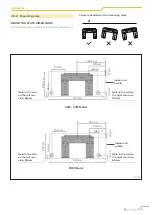
101 mm
192 mm
722 mm
802 mm
517.4 mm
553 mm
144 mm
300 mm
76 mm
148.7 mm
53.5 mm
138 mm
219 mm
34 mm
174.3 mm
151 mm
965 mm
1080 mm
53M Model
35M Model
27M Model
70M Model
Hole in the wall
on the left rear
side, 65 mm
Hole in the wall
on the left rear
side, 65 mm
Hole in the wall
on the left rear
side, 65 mm
Hole in the wall
on the left rear
side, 90 mm
Hole in the wall on
the right rear side,
65 mm
Hole in the wall on
the right rear side,
65 mm
Hole in the wall on
the right rear side,
65 mm
Hole in the wall on the right
rear side, 90 mm
Indoor unit
profile
Indoor unit
profile
Indoor unit
profile
Indoor unit
profile
348.4 mm
426 mm
179 mm
232 mm
136 mm
128 mm
37 mm
43 mm
58 mm
53.5 mm
49 mm
43 mm
40 mm
47 mm
57 mm
47 mm
319 mm
335 mm
49 mm
43 mm
290 mm
297 mm
Fig. 6
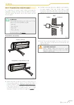
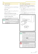
FIX THE MOUNTING PLATE TO THE WALL
1
Remove the screw that fastens the mounting plate to
the back of the indoor unit.
2
Place the mounting plate on the wall in a position
that meets the requirements listed in paragraph
“2.4.1 Installation room” (for detailed information on
the dimensions of the mounting plate see ““Mounting
plate dimensions”.)
3
Drill the holes for the fixing screws in positions that:
– are strong enough and have sufficient capacity to
support the weight of the unit
– match the holes in the mounting plate
4
Fix the mounting plate to the wall using the screws
provided.
5
Check that the mounting plate is in line against
the wall.
l
WARNING
If the wall is made of brick, concrete or similar
materials, drill holes with a diameter of 5 mm
and insert the anchors provided. Then fix the
mounting plate to the wall by tightening the
screws directly into the anchors.
If the wall is made of other materials, use
suitable fasteners and check that they are
properly sealed.
Содержание CLIVET CRISTALLO
Страница 34: ...34 Allegati...
Страница 35: ...35 Allegati...
Страница 70: ...34 Attachments...
Страница 71: ...35 Attachments...
Страница 106: ...34 Pi ces jointes...
Страница 107: ...35 Pi ces jointes...


