19
Installation
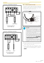
Connections in SINGLESplit configuration
Morsettiera unità INTERNA
alla morsettiera
dell’unità ESTERNA
segnale
alimentazione
W
S
1(L) 2(N)
INDOOR unit terminal block
power supply
signal
to the terminal block of
the OUTDOOR unit
Fig. 14
Connections in MULTISplit configuration
Morsettiera unità INTERNA
alla morsettiera
dell’unità ESTERNA
segnale
alimentazione
W
S
1(L) 2(N)
Morsettiera unità INTERNA
power supply
signal
to the terminal block of
the OUTDOOR unit
Fig. 15
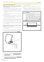
2.4.7 Wrap the pipes and cables
It is necessary to wrap the coolant pipes, drainage pipe
and electrical cables together; this reduces the space
occupied, protects them and insulates them before
passing them through the hole in the wall.
1
Assemble the drainage pipe, coolant pipes and cables
as indicated in “Fig. 16”.
Indoor unit
Space behind
the unit
Refrigerant
piping
Insulating
tape
Electric
cables
Drainage
pipe
Fig. 16
m
CAUTION
– Make sure that the drainage pipe is on the
lower part of the unit. Placement of the
drainage pipe at the top of the unit may
cause the drain pan to overflow, which may
result in fire or water damage.
– When winding the pipes and cables, leave
the ends of the pipes free. These should be
accessible to check for leaks after installation
is complete (see section “3.2 Electrical
dispersion and gas leakage control”
of the
outdoor unit manual).
– When assembling cables, avoid twisting or
tangling the signal cable with other types
of cable.
2
Using vinyl adhesive tape, fasten the drain pipe to the
bottom side of the coolant pipes.
3
Using insulating tape, wrap the electrical cables,
coolant pipes and drainage pipe together. Check that
all components are joined together as indicated in
“Fig. 16”
Содержание CLIVET CRISTALLO
Страница 34: ...34 Allegati...
Страница 35: ...35 Allegati...
Страница 70: ...34 Attachments...
Страница 71: ...35 Attachments...
Страница 106: ...34 Pi ces jointes...
Страница 107: ...35 Pi ces jointes...


