20
Installation
2.4.8 Mounting the indoor unit
CASE “A”: If you have installed a new connection pipe
to the outdoor unit
, proceed as follows:
1
Check that the ends of the coolant pipes are closed
tightly to prevent dust or foreign materials from entering.
2
Slowly pass the unit containing the coolant pipes,
drainage pipe and electrical cables through the hole
in the wall.
3
Hook the top of the indoor unit to the top hook of the
mounting plate.
4
Check that the unit is securely attached to the plate by
applying light pressure to the left and right of the unit.
The unit must not move or swing.
5
Applying uniform pressure, push on the lower half of
the unit. Continue pushing until the unit clicks onto the
hooks located along the base of the mounting plate.
6
Once again check that the unit is securely mounted
on the plate by applying light pressure to the left and
right of the unit.
CASE “B”: If the refrigerant piping is already embedded
in the wall
, proceed as follows:
1
Hook the top of the indoor unit to the top hook of the
mounting plate.
2
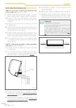
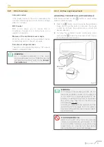
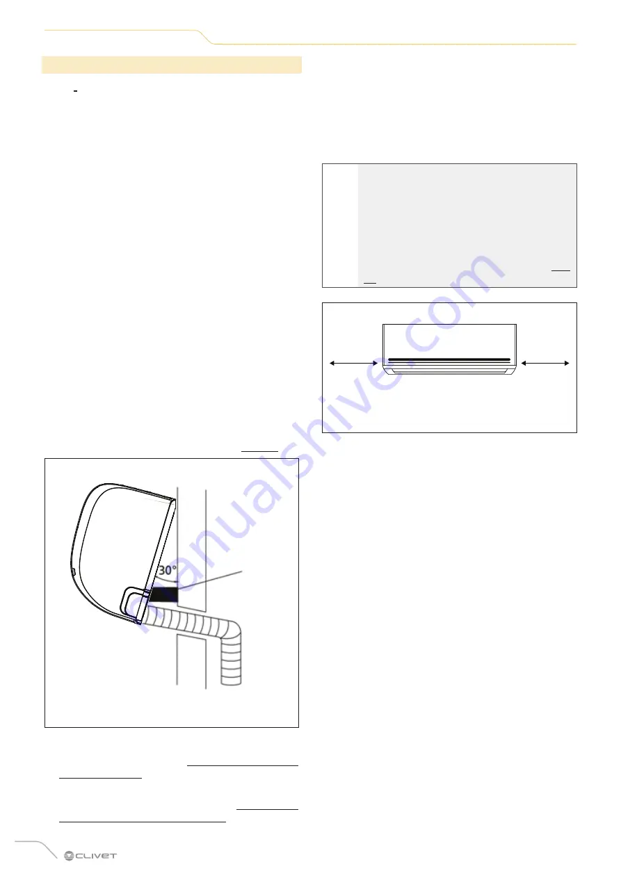
Use a bracket or wedge to lift the unit so that there
is enough space to connect the refrigerant piping,
electrical cables and drainage pipe (see “Fig. 17”).
Wedge
Fig. 17
3
Connect the drainage pipe and refrigerant piping
(for instructions, see section “6 Notions on refrigerant
piping connection” of the outdoor unit manual ).
4
Leave the pipe connection point exposed so that
you can check for leaks (see section “3.2 Electrical
dispersion and gas leakage control” of the outdoor
unit manual).
5
After checking for leaks, wrap the connection point
with insulating tape.
6
Remove the bracket or wedge that holds the unit up.
7
Applying uniform pressure, push on the lower half of
the unit. Continue pushing until the unit clicks onto the
hooks located along the base of the mounting plate.
l
WARNING
THE UNIT IS ADJUSTABLE.
The mounting plate hooks are smaller than the
holes on the back of the unit.
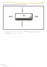
If the space available for connecting the
recessed pipes to the indoor unit is not very
large, the unit can be moved left or right about
30-50 mm, depending on the model (see “Fig.
18”).
Move towards the left or the right
30-50 mm
30-50mm
Fig. 18
Содержание CLIVET CRISTALLO
Страница 34: ...34 Allegati...
Страница 35: ...35 Allegati...
Страница 70: ...34 Attachments...
Страница 71: ...35 Attachments...
Страница 106: ...34 Pi ces jointes...
Страница 107: ...35 Pi ces jointes...


