Chapter 2. Quick Start Guide of Oscilloscope
15
2.10 Use Auto
Once the oscilloscope is properly connected and a valid signal is input, tap the Auto Set button
to
quickly configure the oscilloscope to be the best display effects for the input signal.
Auto is divided into
Auto Set
and
Auto Range
. It is defaulted as Auto Set.6
Auto Set
— Single-time auto, and each time press “Auto”, the screen displays “Auto” in the upper left corner.
The oscilloscope can automatically adjust the vertical scale, horizontal scale and trigger setting according to the
amplitude and frequency of signals, adjust the waveform to the appropriate size and display the input signal.
After adjustments, exit from the auto set, the “Auto” in the upper left corner disappears.
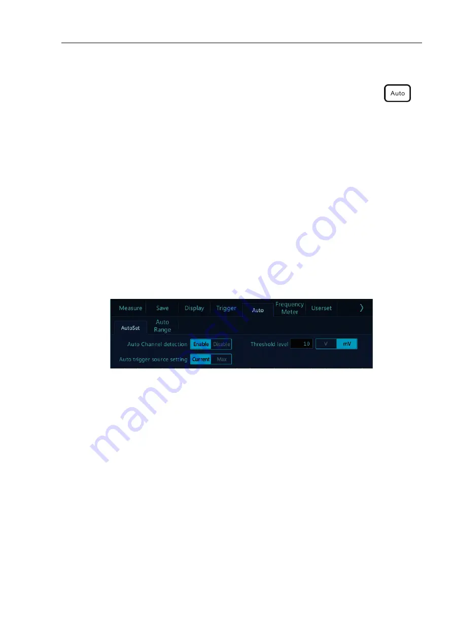
Channels may be automatically opened. Any channel greater or less than the threshold level can be opened or
closed automatically according to the set threshold level. The threshold level can be settable.
Source can be automatically triggered, and the triggered source channel can be automatically set to select priority
to the current signal or to the maximum signal.
Open the main menu. Tap “Auto” to open the auto set menu, including channel open/close setting, threshold
voltage setting and trigger source setting.
Figure 2-9 Open Auto Set
Automatic configuration includes: single channel and multiple channels; automatic adjustment of the horizontal
time base, vertical sensitivity and trigger level of signal; the oscilloscope waveform is inverted off, the bandwidth
limit sets to full bandwidth, it sets as DC coupling mode, the sampling mode is normal; the trigger type is set to
edge trigger and the trigger mode is automatic.
Note: The application of Auto Set requires that the frequency of measured signal is no less than 20Hz, the
duty ratio is greater than 1% and the amplitude is at least 2mVpp. If these parameter ranges are exceeded,
Auto Set will fail.
Содержание TO1072
Страница 1: ......
Страница 2: ...Version Info Version Date Remarks V1 0 2016 10 V2 0 2020 04 ...
Страница 37: ...34 Figure 4 8 DC Coupling Figure 4 9 AC Coupling ...
Страница 117: ...114 Figure 11 15 Locking Interface ...


