background image

VSC8502 Reference Board

VPPD-03822 VSC8502 User Guide Revision 1.0

6

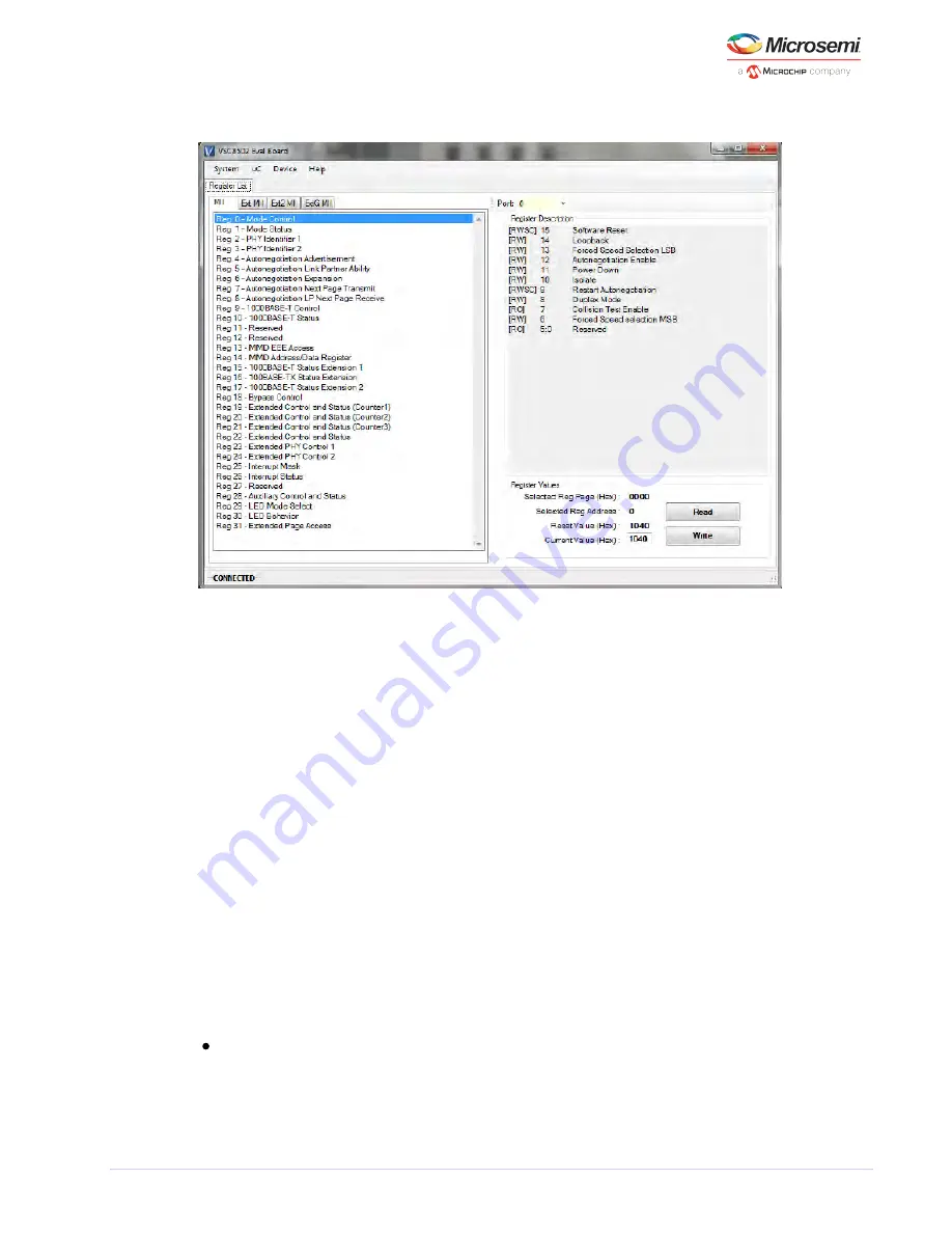
Figure 4 • MII Registers GUI Window

Verify the device is up and running by reading MII Register 0. It should read back 0x1040. Reading back 
all 0’s or all 1’s indicates a problem. For a multi-port device, the corresponding PHY port number is 
accessed via the “Port:” pick list shown above the Register Description in Figure 4.

As Figure 4 indicates, the extended MII register pages can be accessed to read or write by clicking on 
one of the ExtMII/Ext2MII/ExtGMII tabs.

4.3.1

Board Initialization

Once the evaluation board connectivity has been established and confirmed, the PHY should be 
initialized. Initialization can be accomplished by running an init-script sequence, such as performed by 
the pre- and post-reset functions of the PHY API standalone app.

While the init-script sequence may not be required for specific operational modes, an init-script 
sequence is highly recommended to ensure correct performance over the greatest set of user scenarios 
for the PHY. After initialization is performed, refer to the PHY Datasheet section on Configuring the PHY 
and PHY Interfaces for the desired application.

An initialization file, 

, is included in the GUI package. This initialization file will optimize 

vsc8502_init.txt

the copper media interface settings based on the latest factory test result. To execute initialization 
script, click “Device” on the top menu and choose “Load Init Script” option, which will automatically load 
and execute vsc8502_init.txt file in the directory. Once the initialization is completed, it should say 
“LOADED 17 REGISTERS” at the bottom left corner of the GUI Window.

In addition, three other configuration scripts are included:

vsc8502_RGMII_2nsRXCLKdelay.txt: configure the MAC interface to RGMII mode with 2.0 ns RX_CLK 
delay compensation. Note that the board is designed and laid out such that the RGMII DATA, 
CONTROL and CLOCK for each direction are matched in length approximately /-200 ps.

vsc8502_RGMII_2nsGTXCLKdelay.txt: configure the MAC interface to RGMII mode with 2.0ns 

Содержание VSC8502

Страница 1: ...VSC8502 User Guide VSC8502 Reference Board May 2014...

Страница 2: ...5 Software Interface Microcontroller Card 3 3 6 Software Interface Microcontroller Card 4 4 Quick Start 5 4 1 Connecting the Power Supply 5 4 2 PC Software Installation 5 4 3 Connecting to the Board...

Страница 3: ...ory The revision history describes the changes that were implemented in this document The changes are listed by revision starting with the most current publication 1 1 Revision 1 0 Revision 1 0 of thi...

Страница 4: ...also optimizes power consumption in all link operating speeds and features Wake on LAN WOL power management using magic packets This document describes the architecture and usage of the VSC8502RD and...

Страница 5: ...tions Channel 1 Channel 0 GND GND GND GND GND GND GND GND GND GND GND GND RXD2 RXDV_CTL RXD0 RXD3 RXD1 RXCLK RXD3 RXDV_CTL RXD2 RXD0 RXD1 RXCLK TXD2 TXDV_CTL TXD0 TXD3 TXD1 TXCLK TXD3 TXDV_CTL TXD2 TX...

Страница 6: ...board there are three on board regulators that will convert the 5 V supplied by the PC to 1 0 V and 2 5 V for the VSC8502 and 3 3 V for other devices For the VSC8502RD VR board there is only one on bo...

Страница 7: ...the GUI by launching the setup exe file USB communication is assisted by the Silabs USBXpress drive If not present on the PC the user will need to download the USBXpress Development Kit from the Sili...

Страница 8: ...recommended to ensure correct performance over the greatest set of user scenarios for the PHY After initialization is performed refer to the PHY Datasheet section on Configuring the PHY and PHY Inter...

Страница 9: ...mmonly used speed advertisement definitions are as follows Table 2 Auto Negotiation Advertisements MII reg 4 bits 8 7 MII reg 4 bits 6 5 MII reg 9 bits 12 11 MII reg 9 bits 9 8 1000BT Master mode N A...

Страница 10: ...MII 19 7 0 False carrier MII 20 7 0 Disconnects MII 21 7 0 CRC errors ExtMII 23 7 0 5 3 Near End Loopback When the near end loopback test feature is enabled the transmitted data is looped back in the...

Страница 11: ...mine suitability of any products and to test and verify the same The information provided by Microsemi hereunder is provided as is where is and with all faults and the entire risk associated with such...

Отзывы: