


Chapter
2
System Components
2-22
Vision HAWK Smart Camera Guide
–
Mount the camera as required by the application.
–
Connect the Ethernet cable from "B" on the camera to the
network.
–
Connect the power supply to "3" on the QX-1.
–
Connect the photo sensor to "T" on the QX-1.
–
Connect the "Common" cable to "2" on the QX-1 and "A" on the
camera.
–
Plug in the power supply.
2.
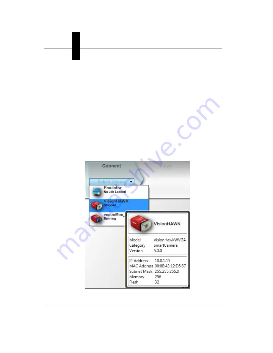
Select your Vision HAWK in the AutoVISION Connect view, create a
job, and adjust camera settings.
AutoVISION's
Connect
view allows you to select your device and
configure its settings, and to create a new job. The
Select Device
dropdown menu provides a list of available devices. Hover the mouse
over a device to see its details.
Содержание Vision HAWK
Страница 1: ...Vision HAWK Smart Camera Guide 83 016800 02 Rev C ...
Страница 6: ...Preface vi Vision HAWK Smart Camera Guide ...
Страница 22: ...Chapter 2 System Components 2 12 Vision HAWK Smart Camera Guide NPN Output for External Load ...
Страница 24: ...Chapter 2 System Components 2 14 Vision HAWK Smart Camera Guide PNP Output for External Load ...
Страница 26: ...Chapter 2 System Components 2 16 Vision HAWK Smart Camera Guide PNP ...
Страница 27: ...Input Output Wiring System Components 2 Vision HAWK Smart Camera Guide 2 17 Input Output Wiring ...
Страница 36: ...Chapter 2 System Components 2 26 Vision HAWK Smart Camera Guide ...
Страница 42: ...Chapter 3 Optics and Lighting 3 6 Vision HAWK Smart Camera Guide ...
Страница 46: ...Appendix A Connector Pinouts A 4 Vision HAWK Smart Camera Guide ...
Страница 52: ...Appendix B Cable Specifications B 6 Vision HAWK Smart Camera Guide ...
Страница 60: ...Appendix C General Specifications C 8 Vision HAWK Smart Camera Guide ...