PPS-
20 LMSM
Precision Stepper Stage
32
Rev: 3.07
MICRONIX USA,LLC
www.micronixusa.com
Reference Manual
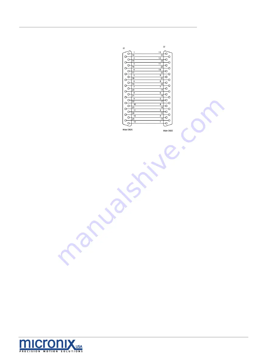
A.6.6
Straight Through 25-Pin Feed Through
Страница 1: ...S e r i e s Reference Manual Precision Linear Motor Stepper Motor Stage Open and Closed Loop Versions PPS 20...
Страница 2: ...PPS 20 Linear Stepper Motor Positioner Stage Reference Manual Rev 3 08 MICRONIX USA LLC Tel 949 480 0538 Fax 949 480 0538 Email info micronixusa com http micronixusa com...
Страница 3: ...Contents 7 4 Installing the PPS 20 LMSM Stage 8 4 1 PPS 20 LMSM Installation 8 4 1 1 General Mounting 8 4 1 2 X Y Mounting 9 5 Connecting the PPS 20 LMSM Stage 10 5 1 Atmospheric Environments 10 5 1 1...
Страница 4: ...Linear Motor Specifications 22 A 3 Magnetic Hall Effect Limit Switches 24 A 4 Open Loop Vacuum Wiring Diagram 25 A 4 1 Straight Through 9 Pin Feed Through 25 A 5 Using an Analog Encoder 26 A 5 1 Anal...
Страница 5: ...micron repeatability High Vacuum 10 6 mbar compatible versions are available Features Stepper Motor travel ranges of 10 mm 18 mm 26 mm and 51 mm Linear Motor travel ranges of 11 mm 18 mm and 25 mm Loa...
Страница 6: ...racteristics Load Characteristics Fx N Fy N Fz N Mx Nm My Nm Mz Nm kax rad Nm kay rad Nm SM 007 5 20 20 0 7 0 7 0 7 LM 003 1 Peak 2 2 0 7 0 7 0 7 Motor option SM 007 LM 003 Speed max mm sec 5 100 Enco...
Страница 7: ...urations 2 1 PPS 20 SM Order Numbers Contact MICRONIX USA for custom applications and stacking configurations Order No PPS 20 2 1 Stepper Motor SM 007 2 10mm Travel 1 18mm Travel 2 26mm Travel 3 51mm...
Страница 8: ...Reference Manual 2 2 PPS 20 LM Order Numbers Contact MICRONIX USA for custom applications and stacking configurations Order No PPS 20 3 Linear Motor LM 003 3 11mm Travel 1 18mm Travel 2 25mm Travel 3...
Страница 9: ...ithin specification at 20 C 5 C unless otherwise specified Be sure to use the stage under the following conditions Mount to a clean and flat surface which is free of debris burrs or dings An indoor at...
Страница 10: ...ing the thru holes Move the carriage to access base mounting pattern Please note it is possible to move the carriage of the linear motor configurations manually without damaging the stage however for...
Страница 11: ...r configurations manually without damaging the stage however for stepper versions the motor must be driven by a controller to reposition the carriage Stepper Motor Linear Motor Travel A B Travel A B 1...
Страница 12: ...ion refer to the appropriate MMC controller manual 5 1 1 Open Loop Installation Wiring Diagram Connecting the PPS 20 LMSM stage in an open loop configuration only requires that the D sub 9 Pin male Mo...
Страница 13: ...anual 5 1 2 Closed Loop Encoder Installation Wiring Diagram Using the PPS 20 LMSM stage with an encoder requires a closed loop compatible controller that recognizes encoder feedback Connect the stage...
Страница 14: ...PPS 20 LMSM Precision Stepper Stage 12 Rev 3 07 MICRONIX USA LLC www micronixusa com Reference Manual 5 1 2 2 MII 6000 Digital Encoder Wiring Diagram Stepper Motor Version Linear Motor Version...
Страница 15: ...r for closed loop with MII 6000 digital encoder 5 2 2 Open loop Installation Wiring Diagram Connecting an open loop PPS 20 LMSM stage in a vacuum chamber requires the use of a feed through connector a...
Страница 16: ...wiring for a straight through feed through not a cross over gender bender MICRONIX USA supplies test connectors that simulate the vacuum feed through to allow for functionality testing prior to instal...
Страница 17: ...A LLC www micronixusa com Reference Manual 6 Technical Specifications 6 1 Dimensions 6 1 1 PPS 20 Stepper Motor Analog Encoder TRAVEL A B C D 12 20 16 41 3 61 3 18 30 16 41 3 72 1 26 40 36 35 7 75 8 5...
Страница 18: ...3 07 MICRONIX USA LLC www micronixusa com Reference Manual 6 1 2 PPS 20 Stepper Motor MII 6000 Digital Encoder TRAVEL A B C D 10 20 16 41 3 61 3 18 30 16 41 3 72 1 26 40 36 35 7 75 8 51 80 50 32 1 110...
Страница 19: ...17 Rev 3 07 MICRONIX USA LLC www micronixusa com Reference Manual 6 1 3 PPS 20 Linear Motor Analog Encoder L TRAVEL A B C D E F 20 11 6 1 2 15 16 40 30 18 6 1 2 25 16 54 5 40 25 10 3 6 35 36 66 8 Grey...
Страница 20: ...v 3 07 MICRONIX USA LLC www micronixusa com Reference Manual 6 1 4 PPS 20 Linear Motor MII 6000 Digital Encoder L TRAVEL A B C D E F 20 11 6 1 2 15 16 40 30 18 6 1 2 25 16 54 5 40 25 10 3 6 35 36 66 8...
Страница 21: ...mples Additional Configurations available upon request Additional configurations available upon request Note Stacking compatibility for all motor configurations Positioning according to No Adapters X...
Страница 22: ...ity of the stage Follow the Installation Preparation requirements and use proper cable management to ensure a clean and safe operating environment Allow for easy access to the stage in case of servici...
Страница 23: ...ifications Stepper Motor Pin Function Wire Color 1 Motor A Yellow 2 Motor A Green 3 Motor B Black 4 Motor B Red 5 N A N A 6 Limit Switch Violet 7 Limit Switch Blue 8 5V Orange 9 Ground Brown Stepper M...
Страница 24: ...e 0 81 N 2 9 oz Force Constant 0 77 N A 2 8 oz A Back EMF Constant 0 77 V m s 0 020 V in s Stroke 12 7 mm 0 50 in Coil Clearance Per Side 0 33 mm 0 013 in Coil Assy Mass 6 4 gr 0 23 oz Body Mass 10 6...
Страница 25: ...Force 10 Duty Cycle 2 20 N 7 9 oz Continuous Force 0 70 N 2 5 oz Force Constant 0 76 N A 2 7 oz A Back EMF Constant 0 76 V m s 0 019 V in s Stroke 25 4 mm 1 000 in Coil Clearance Per Side 0 33 mm 0 01...
Страница 26: ...ature range 40 to 150 C and exceptionally long life The hall effect limit switches are factory calibrated to ensure advertised travel length and cannot be adjusted by the customer A 3 1 Hall Effect Li...
Страница 27: ...ric Motor Connector Female Dsub 9 Pin to Male Dsub 9 Pin 1 5m Wiring Diagram A 4 1 Straight Through 9 Pin Feed Through Stepper Motor Connector Pinout Description Color L1 L2 L3 L4 L5 Motor Phase A Yel...
Страница 28: ...PS 20 LMSM stage with internal Analog encoder will be supplied with a 15 pin connector that incorporates both motor and encoder signals A 5 2 Encoder Pin Out A 5 3 Operating and Electrical Specificati...
Страница 29: ...ospheric Encoder Module Female Dsub 25 Pin to Female Dsub 9 Pin Wiring Diagram Encoder Motor Stepper Motor Connector Pinout Description Color L1 L2 L3 L4 L5 L6 Motor B Orange 1 1 13 13 Brown 4 Ground...
Страница 30: ...proper encoder alignment A Red or Yellow Signal Level LED indicates misalignment of the Encoder Head if this occurs contact MICRONIX USA Do not adjust the Encoder Head or scale For more information r...
Страница 31: ...ial Inverse signals are not shown for clarity Note At some interpolations values the index pulse may be aligned with other states of A or B than the ones shown Above are with reference to the sensor s...
Страница 32: ...PPS 20 LMSM Precision Stepper Stage 30 Rev 3 07 MICRONIX USA LLC www micronixusa com Reference Manual...
Страница 33: ...r B Blue 2 2 12 12 White Brown TP 3 5V Orange 15 15 24 24 Red 8 Motor A Red 3 3 11 11 Green 2 Limit Blue 16 16 23 23 White Violet TP 7 Motor A Yellow 4 4 10 10 White Green TP 1 Limit Violet 17 17 22 2...
Страница 34: ...PPS 20 LMSM Precision Stepper Stage 32 Rev 3 07 MICRONIX USA LLC www micronixusa com Reference Manual A 6 6 Straight Through 25 Pin Feed Through...