background image


Technical and Functional Details


Peripheral Controls


GDUTUG500/01 

CE-500 MDT Hardware Guide


35 / 97 


NOTE: 

One of these inputs (In1) is also used to power on the device from the shutdown state. 
For proper power management implementation, the input must be connected to the 
vehicle's ignition switch. The platform provides various software control options for this 
essential feature. For more details, refer to the 

Digital I/O

 and 

Power Management


sections of the 

Developers Guide

Table 2 

– Electrical Parameters of Input States  

Input State 

Typical 

Minimum 

Maximum 

Low 

0V 

-30V 

5V 

High 

12V-24V 

+8V 

+30V 

D

D

i

i

g

g

i

i

t

t

a

a

l

l


O

O

u

u

t

t

p

p

u

u

t

t


The platform provides a digital output (Open Collector) for external peripherals control. This signal is 
connected to the Main Terminal “Con1” connector, which is located on the bottom panel of the device. 

Table 3 

– Electrical Parameters of Open Collector Output 

Parameter 

Value 

Maximum switchable voltage 

+VIN 

Maximum switchable current 

300mA 

For the disposition map of the Digital Input1 and Digital Output signals of this port on 

Main Terminal 

“Con1” Connector

, see page 

38

.


For the disposition map of the Digital Input2 signal of this port on 

Enhanced Terminal “Con2” Connector

see page 

39

.


In the Fixed-mount mode, the Digital Input1 and Digital Output require the Main Accessory Cable and 
Digital Input2 requires the Enhanced Accessory Cable connection. 

For the disposition map of the Digital Input1 and Digital Output on Power-Adaptor-Box of the Main 
Accessory Cable, see 

Power-Adaptor-Box to +Vin Connector

on page 

64

. 

For the disposition of the Digital Input2 signal on the Accessory Cables Enhanced Interface cable, see 

COM2 Connector

on page 

65.


 For the disposition map of the Digital Input1 and Digital Output on the Device Cradle, see 

+Vin 

Connector

on page 

76

. 

For the disposition of the Digital Input2 signal on the Device Cradle, see 

COM2

 Connector, on page 
78

.  

Содержание CE-504

Страница 1: ...Revision C January 2011 C CE E 5 50 00 0 M Mo ob bi il le e D Da at ta a T Te er rm mi in na al l H Ha ar rd dw wa ar re e G Gu ui id de e...

Страница 2: ...ithout prior written approval from Micronet Ltd Information in this manual is subjected to change without notice Micronet shall have neither liability nor responsibility to any person or entity with r...

Страница 3: ...evelopment Tool Kit 12 Hardware 12 Software 12 Documentation 12 CE 500 Platform Key Feature Specifications 13 CE 500 Platform Optional Modules 15 CE 500 Platform Accessories 16 CE 50X Device Component...

Страница 4: ...al Serial Bus Communication 32 Ethernet Communication Option 34 Peripheral Controls 34 Digital I O 34 Analog Input 36 1 Wire Interface 36 Terminal Connector Signal Maps 37 Overview 37 Pinout of Connec...

Страница 5: ...Support 69 J1708 Convertor Box 69 RS 422 Convertor Box 69 Device Cradle 70 Overview 70 CE 500 Device Basic Cradle Components 71 CE 500 Device Enhanced Cradle Components 73 Device Cradle Connectors 75...

Страница 6: ...Table of Contents GDUTUG500 01 CE 500 MDT Hardware Guide 6 97 Physical Characteristics 94 Appendices 95 Appendix A 95 Regulations Certifications 95...

Страница 7: ...a ac ce e R Re ev vi is si io on n H Hi is st to or ry y Revision Date Change A February 2010 Document created B March 2010 Adding new power management functionality B 1 April 2010 Keypad keys names h...

Страница 8: ...ce and possibly have caused damage immediately turn off the power and contact your original dealer or an authorized service provider Continued usage is dangerous and may result in fire or electric sho...

Страница 9: ...tap water and a physician consulted P Po ow we er r S Su up pp pl ly y WARNING Do not use the CE 500 at a voltage other than specified Doing so may result in fire or electric shock Avoid conditions th...

Страница 10: ...re enables setting various factory set configurations and performing in field hardware upgrades using plug in modules The layered architecture provides a proof and cost effective design by simplifying...

Страница 11: ...nd large programmable function and control keys P Ph hy ys si ic ca al l I In nt te er rf fa ac ce es s Both CE 504 and CE 507 provide the following physical interfaces USB Serial RS232 ports Dedicate...

Страница 12: ...ge provides all tools required for application development quick start product testing and product evaluation The Developers Package includes 20 hours of technical support and contains all essential h...

Страница 13: ...ssional license available optional Application development environment Microsoft Visual Studio 2005 2008 Processor TI Omap 3503 ARM Cortex A8 Core RAM 256MB Flash 512MB Memory card support SD MMC SDHC...

Страница 14: ...ts 1 X open collector output Analog Input 0V 30V 1 Wire Interface Dallas ID memory button support Power Input power 5V DC power input by device side panel connector Direct vehicle battery connection 1...

Страница 15: ...ections Ethernet LAN port requires Enhanced accessory cable or device cradle option LAN 10 100Mbit sec J1939 port requires CANBus accessory Cable or Device Cradle option CANBus V2 0B External Audio re...

Страница 16: ...s J1939 CANBus interface cable Device Con3 to CAN connector Audio interface cable Device Con4 to External Audio connectors Interface Connections J1708 Adaptor requires Enhanced accessory cable uses Se...

Страница 17: ...c co om mp po on ne en nt ts s For more information on CE 504 front panel components see Display on page 26 Customized Front Panel Label on page 30 Internal Speakers on page 30 Keypad on page 27 Ligh...
Страница 18: ...el Front Panel components For more information on CE 507 front panel components see Display on page 26 Customized Front Panel Label on page 30 Internal Speakers on page 30 Keypad on page 27 Light Sens...

Страница 19: ...CE 50X bottom panel components see Main Terminal Con1 Connector on page 38 Enhanced Terminal Con2 Connector on page 39 Optional External Video and CANBus Con3 Connector on page 41 Optional External A...

Страница 20: ...or Slot and Slot cover components For more information on CE 50X Right side panel components see Device connectors slot on page 25 Memory Card Support on page 24 USB OTG Port on page 32 5V Power in co...

Страница 21: ...C Co om mp po on ne en nt t Figure 5 CE 50X Model Left Side Panel and SIM Card Slot cover components For more information on CE 50X Left side panel components see SIM card slot on page 53 Device Conne...

Страница 22: ...01 CE 500 MDT Hardware Guide 22 97 Figure 6 CE 50X Model Rear Panel components For more information on CE 50X Rear panel components see Mounting Arm screw inserts on page 85 Stylus on page 27 Stylus M...

Страница 23: ...d operating system components refer to CE 500 Operating System Specifications at http www micronet co il CE 500_Operating_system html For more details on device s operating system architecture refer t...

Страница 24: ...ry is partially allocated for system image storage and Flash File System partition accessible for the applications as a persistent data storage drive Approximately 64 MB of the Flash memory is allocat...

Страница 25: ...move the rubber cover by removing the rubber snap in the center of the cover 2 Push the plastic cover into the same place After the plastic cover is inserted this cover can only be broken physically b...

Страница 26: ...e modules see page 93 D Di is sp pl la ay y The CE 504 device model provides a 4 3 Touch Color display with WQVGA 480 X 272 pixels resolution The CE 507 device model provides a 7 Touch Color display w...

Страница 27: ...ys to enable the most commonly used application functions L Li ig gh ht t S Se en ns so or r The platform provides a light sensor component which is located on the front panel Applications use this se...

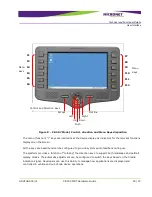
Страница 28: ...l Details User Interface GDUTUG500 01 CE 500 MDT Hardware Guide 28 97 Figure 7 CE 504 Model Control direction and Menu Keys disposition Control and Direction Keys Menu keys F1 F2 F3 F4 Decline Up Left...

Страница 29: ...igured to provide system audio feedback during use The platform provides a function of rotating the direction keys to support both landscape and portrait display modes The automatic adjustment can be...

Страница 30: ...l charge per unit based on quantity Once printed Micronet will store the labels and use them for orders placed for this product Figure 9 Customized Front Panel Label A Au ud di io o S Su up pp po or r...

Страница 31: ...he API When setting up these components dedicated CODEC channels are used to manage audio components including system sound voice calls optional text to speech and voice recognition engines C Co om mm...

Страница 32: ...port requires Enhanced Accessory Cable connection For the disposition map of the signals of this port on the Enhanced Accessory Cable see Accessories Enhanced Interface cable COM2 Connector on page 65...

Страница 33: ...G port is limited to provide up to 100mA of power consumption for non self powered client devices The USB OTG port supports USB2 0 low full and high speeds of communication standard The USB OTG connec...

Страница 34: ...ion requirement with the device order This port is fully compliant with IEEE 802 3 802 3u standards and supports 10BASE T and 100BASE TX functionalities For the disposition map of the signals of this...

Страница 35: ...trical Parameters of Open Collector Output Parameter Value Maximum switchable voltage VIN Maximum switchable current 300mA For the disposition map of the Digital Input1 and Digital Output signals of t...

Страница 36: ...of this signal on the Device Cradle see COM2 Connector on page 78 1 1 W Wi ir re e I In nt te er rf fa ac ce e The platform provides the 1 Wire Interface Port connected to the Main Terminal Con1 conne...

Страница 37: ...nfiguration The power communication and I O signals in the Basic configuration and the Video CANBus and Audio signals in the Full configuration All pins are ESD protected against electrostatic dischar...

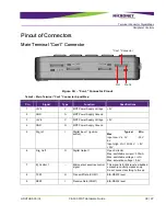
Страница 38: ...Power Supply Ground 3 5Vin V MDT Power Supply Voltage 5V 4 GND G MDT Power Supply Ground 5 Dig_In1 I Digital Input 1 Ignition switch Typical Min Max Input Low VIL 0V 30V 6V Input High VIH 12V 24V 8V 3...

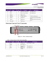
Страница 39: ...iversal Serial Bus Specification Rev 2 15 USB D B USB Data Universal Serial Bus Specification Rev 2 16 USB GND G USB Ground E En nh ha an nc ce ed d T Te er rm mi in na al l C Co on n2 2 C Co on nn ne...

Страница 40: ...his pin 9 M_Control 4 Micronet accessories control signal This signal is for Micronet embedded accessory control purposes only Do not connect anything to this pin 10 M_Control 5 Micronet accessories c...

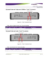
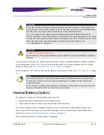
Страница 41: ...Con3 Connector Pinout Table 6 Video and CANBus Terminal Con3 Connector Signal Map Pin Signal Type Function Specifications To be documented O Op pt ti io on na al l E Ex xt te er rn na al l A Au ud di...

Страница 42: ...power source The device power in signals VIN and GND are connected in parallel to two entities 5 5V V P Po ow we er r i in n c co on nn ne ec ct to or r Located on the device right side panel Figure 1...

Страница 43: ...le or connected to the solution peripherals the device can be powered through the Terminal Connector by the Main Interface Accessory cable or through the device Cradle when the device is portable For...

Страница 44: ...e disposition of the 12V 24V Vin and Ground signals on the Power Adaptor Box of the Main Accessory Cable see Power Adaptor Box to Vin Connector on page 64 For the position 12V 24V Vin and Ground signa...

Страница 45: ...tion to prevent battery degradation Micronet delivers the battery pack charged for 40 of capacity In this case the shelf lifetime of the pack is about six months If you did not use the battery during...

Страница 46: ...for specific usages For more information on the CE 500 platform power management architecture refer to Power Management section in the Developers Guide The OS registry can be resets to factory defaul...

Страница 47: ...I function System Power management timeouts Triggers to Exit the State Pressing Push key RTC alarm notification Digital Input 1 signal Inserting the device to cradle NOTE These events resume all proce...

Страница 48: ...lding the Decline key for 3 seconds Calling the API function Triggers to Exit the State Pressing Push key RTC alarm notification Digital Input 1 signal Figure 17 Device manual software Shutdown W Wa a...

Страница 49: ...rated CE 500 device State characteristics Registry is flushed settings are preserved RTC is not alive system time is reset Memory allocation is not preserved Triggers to Enter the State Pressing F1 F2...

Страница 50: ...s saving data to the Flash storage because it may damage the Flash File system S Se et tt ti in ng g R Re eg gi is st tr ry y t to o F Fa ac ct to or ry y D De ef fa au ul lt ts s To reset the registr...

Страница 51: ...format the Flash memory storage partition follow the steps Shutdown the CE 500 device first by pressing the Decline key for 3 seconds Pressing and holding simultaneously F2 Left and Right keys Pressi...

Страница 52: ...ace modules require certain accessory cables for connection in the Fixed device operation mode or enhanced device cradle in the Fixed Mobile operation mode W Wi ir re el le es ss s C Co om mm mu un ni...

Страница 53: ...of the module using the integrated device speakers and microphone In addition developers can use the optional external audio module for external microphone and speaker connections Bluetooth headset c...

Страница 54: ...ided Starts Supports SBAS WAAS EGNOS MSAS GAGAN SuperSense Indoor GPS 160 dBm tracking sensitivity Position Accuracy Autonomous 2 5 m SBAS 2 0 m High immunity to jamming Protocols support NMEA Input o...

Страница 55: ...consumer of the platform If your solution requires Portable operation of the CE 500 device including cellular communication consider the Enhanced battery option while specifying your device configura...

Страница 56: ...i ir re el le es ss s L LA AN N a an nd d B Bl lu ue et to oo ot th h C Cl la as ss s2 2 M Mo od du ul le e S Sp pe ec ci if fi ic ca at ti io on ns s Table 9 Wireless LAN and Bluetooth Class2 Module...

Страница 57: ...s Bluetooth Bluetooth 2 1 EDR data rates of 1 2 and 3Mbps Operating Range Open Space 300m indoor 100m for WLAN Minimum 10m indoor for Bluetooth The transmission speed may vary according to environment...

Страница 58: ...UG500 01 CE 500 MDT Hardware Guide 58 97 E Ex xt te er rn na al l V Vi id de eo o M Mo od du ul le e To be documented A Ad dd di it ti io on na al l I In nt te eg gr ra at te ed d O Op pt ti io on ns...

Страница 59: ...rs always exist on the device panel Additional accessory cables are used to support optional platform features and require the relevant optional device module The pinout and types of the interface con...

Страница 60: ...The length of each accessory cable is 1 5 meter Figure 23 Accessory Connectors Bottom Panel For more information on CE 500 front panel components see Main Interface Cable on page 61 Enhanced Interface...

Страница 61: ...rated power adaptor box This box converts the vehicle 12V or 24V power signal to 5V as required by the device Figure 24 Main Interface Cable M Ma ai in n I In nt te er rf fa ac ce e C Ca ab bl le e C...

Страница 62: ...SB B C Co on nn ne ec ct to or r Connector type USB type A female Figure 26 Main Interface Cable USB Connector Pinout Table 11 USB Connector Signal Map Pin Signal Function 1 USB 5V 5V USB Power Out 2...

Страница 63: ...gnal to 5V DC which the device s main cable accepts Figure 28 Power Adapter Box WARNING Metal Power Adapter Box is installed for installation in a restricted access location P Po ow we er r A Ad da ap...

Страница 64: ...ctor type Molex Micro Fit 3 0 4 pin plug Figure 30 Power Adapter Box to MDT Connector Pinout Table 12 Power Adaptor Box Vin Connector Signal Map Pin Signal Type Function Specifications Wire Size AWG R...

Страница 65: ...nc ce ed d I In nt te er rf fa ac ce e C Ca ab bl le e c co on nn ne ec ct to or rs s S Si ig gn na al l M Ma ap p C CO OM M2 2 C Co on nn ne ec ct to or r Connector type Molex Micro Fit 3 0 8 pin pl...

Страница 66: ...LAN interface is an optional platform feature The interface signals described below present on this connector only if the device supports these signals Otherwise the connector pins are not connected a...

Страница 67: ...ices connection Do not connect anything else to these signals Figure 34 M_Control1 Connector Pinout V Vi id de eo o a an nd d C CA AN NB Bu us s I In nt te er rf fa ac ce e C Ca ab bl le e To be docum...

Страница 68: ...S Se er ri ie es s C Co on nn ne ec ct to or r A Molex 43025 series connector wall power supply adapter 110V 220V AC to 12V DC for connecting to the CE 500 Main Interface cable DC to DC convertor or...

Страница 69: ...0 01 CE 500 MDT Hardware Guide 69 97 I In nt te er rf fa ac ce e S Su up pp po or rt t J J1 17 70 08 8 C Co on nv ve er rt to or r B Bo ox x To be documented R RS S 4 42 22 2 C Co on nv ve er rt to or...

Страница 70: ...tinue to operate using the internal battery However the device loses connectivity to the Cradle interface connections Two models of the Device Cradle are available Basic which provides two Cradle Devi...

Страница 71: ...dl le e C Co om mp po on ne en nt ts s Figure 37 CE 500 Device Basic Cradle Front Side For more information on Basic Cradle front panel components see Main Terminal Con1 Connector on page 38 Enhanced...

Страница 72: ...n on Basic Cradle rear panel components see Vin Connector on page 76 LAN connector on page 78 COM1 Connector on page 76 USB Connector on page 77 COM2 Connector on page 78 Mounting Arm screw inserts on...

Страница 73: ...re information on Enhanced Cradle front panel components see Main Terminal Con1 Connector on page 38 Enhanced Terminal Con2 Connector on page 39 Optional External Video and CANBus Con3 Connector on pa...

Страница 74: ...Vin Connector on page 76 LAN connector on page 78 COM1 Connector on page 76 COM1 Connector Vin Connector USB Connector Video in1 connector Full Video in2 connector LAN connector COM2 Connector Spare...

Страница 75: ...ew w Instead of the interfaces that require the standard type of connectors such as USB and Ethernet all other signals are located on the CE 500 Device Cradle by Molex Micro Fit 3 0 Plug connector ty...

Страница 76: ...hed to this connector Connector type Molex Micro Fit 3 0 4 pin plug Figure 42 Cradle Vin Connector Pinout Table 15 Cradle Vin Connector Signal Map Pin Signal Type Function Specifications Wire Size AWG...

Страница 77: ...TXD1 Transmit Data COM1 28 2 RTS1 Request To Send COM1 28 3 DGND Digital Ground 28 4 RXD1 Receive Data COM1 28 5 CTS1 Clear To Send COM1 28 6 N C Not connected U US SB B C Co on nn ne ec ct to or r Co...

Страница 78: ...ector Signal Map Pin Signal Function Wire Size AWG Required 1 TXD2 Transmit Data COM2 28 2 Dallas One Wire Interface DALLAS ID Button Interface Port 28 3 Dig_In2 Digital Input 2 28 4 N C Not connected...

Страница 79: ...24 4 N C Not connected 5 N C Not connected 6 LAN_RX Optional Ethernet LAN Receive Data 24 7 N C Not connected 8 N C Not connected NOTE The Ethernet LAN interface is an optional feature of the platfor...

Страница 80: ...vice Cradle model only Figure 48 Cradle RCA Video Connector NOTE The External Video interface support is an optional feature of the platform This interface signals are only located on this connector i...

Страница 81: ...tional feature of the platform This interface signals are located on this connector only if the device supports these signals Otherwise the connector pins are not connected and must not be used M Mi i...

Страница 82: ...these signals Otherwise the connector pins are not connected and must not be used C CA AN NB Bu us s C Co on nn ne ec ct to or r To be documented This connector is provided by the enhanced Device Crad...

Страница 83: ...receptacle connector type The same type of connector with the same pinout is located on the rear panel of the Cradle that provides this interface This concept is relevant for all interface connectors...

Страница 84: ...ll connected peripheral operate properly 6 In the Fixed mounted mode fix the Accessory cables on the CE 50X device with cable mounting screws M Me ec ch ha an ni ic ca al l I In ns st ta al ll la at t...

Страница 85: ...anical strains when the detachable terminal options are used A correct installation location and surface must be chosen as along with installation materials M Mo ou un nt ti in ng g A Ar rm m The Micr...

Страница 86: ...Device Installation Mechanical Installation GDUTUG500 01 CE 500 MDT Hardware Guide 86 97 Component Picture Component Name Screw Washer Mounting Arm Base ball...

Страница 87: ...ase of the mounting arm assembly to the dashboard or cabin 3 Assemble the stand parts on the mounting arm base 4 Attach the mounting arm to the rear panel of the device using the mounting screws inser...

Страница 88: ...dware Guide 88 97 M Mo ou un nt ti in ng g a ar rm m s sc cr re ew ws s d di im me en ns si io on n Proper screws for mounting non Micronet mounting arm based on the device inserts depth and the arm s...

Страница 89: ...dashboard or cabin 3 Assemble the stand parts on the mounting arm base 4 Attach the mounting arm to the rear panel of the device Cradle using the mounting screws inserts 5 Perform electrical installa...

Страница 90: ...dware Guide 90 97 M Mo ou un nt ti in ng g a ar rm m s sc cr re ew ws s d di im me en ns si io on n Proper screws for mounting non Micronet mounting arm based on the cradle inserts depth and the arm s...

Страница 91: ...I In ns se er rt ti in ng g t th he e D De ev vi ic ce e i in nt to o t th he e C Cr ra ad dl le e To insert the device into the cradle 1 Insert the device into the cradle slot from the top Verify th...

Страница 92: ...97 R Re em mo ov vi in ng g t th he e D De ev vi ic ce e f fr ro om m t th he e C Cr ra ad dl le e To remove the device from the cradle 1 To unlock the device push and hold the Release knob on the bo...

Страница 93: ...odules Installation Mechanical Installation GDUTUG500 01 CE 500 MDT Hardware Guide 93 97 1 10 0 O Op pt ti io on na al l F Fe ea at tu ur re e M Mo od du ul le es s I In ns st ta al ll la at ti io on...

Страница 94: ...h 6 30 inch 160 mm Height 3 40 inch 87 mm Depth 1 50 inch 38 mm Weight w Battery 14 70 oz 410 Gram Weight w o Battery 13 50 oz 380 Gram CE 507 Dimensions Weight Width 8 80 inch 225 mm Height 6 40 inch...

Страница 95: ...rk ki in ng g C Cl la as ss s B B LVD Directive 2006 95 EC 73 23 EEC According to standards EN60950 1 R TTE Directive 1999 5 EC According to standards EN301 489 1 17 EN300 328 for Wi Fi Bluetooth Conf...

Страница 96: ...iguration This equipment has been tested and found to comply with the limits for a Class A digital device pursuant to Part 15 of the FCC rules These limits are designed to provide reasonable protectio...

Страница 97: ...y y e el le ec ct tr ro om ma ag gn ne et ti ic c f fi ie el ld ds s To comply with FCC Section 1 307 b 1 for human exposure to radio frequency electromagnetic fields implement the following instructi...

Отзывы: