6
Micron® 100W Soldering Station
IMPORTANT:
The temperature above 410°C is not recommended for normal soldering functions, but
can be used for short periods of time when high temperatures are required. Please note that the lead free
solder alloys require a higher soldering temperature which shortens tip life.
Operating Instructions
Ensure that the mains input voltage is between 220-240V before beginning use. Check carefully for any
damage during transportation.
This unit contains:
1. Solder handle.
2. Iron holder with brass tip cleaner.
3. AC power cord with plug.
Operating Procedures:
1. Ensure that the base unit power switch is in the “OFF” position.
2. Plug in solder handle and connect AC power cord.
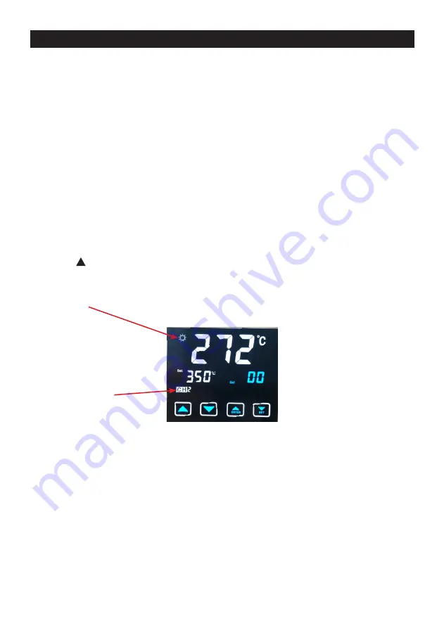
3. Turn mains power switch to “ON” position. The LCD touchscreen will illuminate many icons, most of
which are non-functioning indicators. Those icons described in the functions table above are the symbols
for functions that are enabled on this model. Other icons may be relevant for future models. (See Figure 1)
4. Press the key up until the temperature reaches 250° with CH0 displayed as the default channel.
Then tin the surface of the tip by applying a new covering of solder after being warmed to protect tip and
extend its life. (CH0 is NOT a preset channel and has no memory storage.)
5. When the Display temperature reaches the desired Set temperature, the heating indicator light / sym-
bols (sunlight icon) will flicker and flash and maintain the set temperature. The unit is now ready for normal
operation.
TEMPERATURE CHANNELS STORAGE
This touchscreen model has a memory channels for three pre-set temperature levels – CH1, CH2, CH3.
These channels are accessed by pressing the white button on the right side of the screen. Each time you
press this button, the screen with scroll to the next CH number in sequence, and eventually loops back to
CH1. If you leave the channel memory on a certain number, the set temperature will change to that level,
and the display temperature will begin to adjust to match the set temperature.
To set the value for any channel memory, follow these steps in order:
1. Press and hold the ‘SET’ button on the touchscreen for 3 second, regardless of which CH is currently
allocated. When the SET button is released, the CH0 number will be flashing.
2. Press the SET button again. The CAL icon will be flashing. (Temperature adjust buttons to set CAL
temperature correction value! ^)
3. Press SET again to move to CH1, and again for CH2, CH3. Choose any one you wish to set. (The SET
Channel 2
displayed


