


dsPIC30F6010
DS70119B-page 90
Advance Information
2004 Microchip Technology Inc.
15.7
Dead-Time Generators
Dead-time generation may be provided when any of
the PWM I/O pin pairs are operating in the Comple-
mentary Output mode. The PWM outputs use Push-
Pull drive circuits. Due to the inability of the power out-
put devices to switch instantaneously, some amount of
time must be provided between the turn off event of one
PWM output in a complementary pair and the turn on
event of the other transistor.
The PWM module allows two different dead-times to be
programmed. These two dead-times may be used in
one of two methods described below to increase user
flexibility:
• The PWM output signals can be optimized for dif-
ferent turn off times in the high side and low side
transistors in a complementary pair of transistors.
The first dead-time is inserted between the turn
off event of the lower transistor of the complemen-
tary pair and the turn on event of the upper tran-
sistor. The second dead-time is inserted between
the turn off event of the upper transistor and the
turn on event of the lower transistor.
• The two dead-times can be assigned to individual
PWM I/O pin pairs. This Operating mode allows
the PWM module to drive different transistor/load
combinations with each complementary PWM I/O
pin pair.
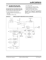
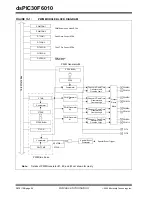
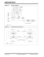
15.7.1
DEAD-TIME GENERATORS
Each complementary output pair for the PWM module
has a 6-bit down counter that is used to produce the
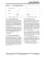
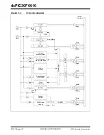
dead-time insertion. As shown in Figure 15-4, each
dead-time unit has a rising and falling edge detector
connected to the duty cycle comparison output.
15.7.2
DEAD-TIME ASSIGNMENT
The DTCON2 SFR contains control bits that allow the
dead-times to be assigned to each of the complemen-
tary outputs. Table 15-1 summarizes the function of
each dead-time selection control bit.
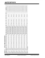
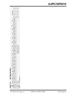
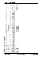
TABLE 15-1:
DEAD-TIME SELECTION BITS
15.7.3
DEAD-TIME RANGES
The amount of dead-time provided by each dead-time
unit is selected by specifying the input clock prescaler
value and a 6-bit unsigned value. The amount of dead-
time provided by each unit may be set independently.
Four input clock prescaler selections have been pro-
vided to allow a suitable range of dead-times, based on
the device operating frequency. The clock prescaler
option may be selected independently for each of the
two dead-time values. The dead-time clock prescaler
values are selected using the DTAPS<1:0> and
DTBPS<1:0> control bits in the DTCON1 SFR. One of
four clock prescaler options (T
CY
, 2T
CY
, 4T
CY
or 8T
CY
)
may be selected for each of the dead-time values.
After the prescaler values are selected, the dead-time
for each unit is adjusted by loading two 6-bit unsigned
values into the DTCON1 SFR.
The dead-time unit prescalers are cleared on the fol-
lowing events:
• On a load of the down timer due to a duty cycle
comparison edge event.
• On a write to the DTCON1 or DTCON2 registers.
• On any device Reset.
Bit
Function
DTS1A
Selects PWM1L/PWM1H active edge dead-time.
DTS1I
Selects PWM1L/PWM1H inactive edge
dead-time.
DTS2A
Selects PWM2L/PWM2H active edge dead-time.
DTS2I
Selects PWM2L/PWM2H inactive edge
dead-time.
DTS3A
Selects PWM3L/PWM3H active edge dead-time.
DTS3I
Selects PWM3L/PWM3H inactive edge
dead-time.
DTS4A
Selects PWM4L/PWM4H active edge dead-time.
DTS4I
Selects PWM4L/PWM4H inactive edge
dead-time.
Note:
The user should not modify the DTCON1
or DTCON2 values while the PWM mod-
ule is operating (PTEN =
1
). Unexpected
results may occur.
Содержание dsPIC30F6010
Страница 12: ...dsPIC30F6010 DS70119B page 10 Advance Information 2004 Microchip Technology Inc NOTES...
Страница 32: ...dsPIC30F6010 DS70119B page 30 Advance Information 2004 Microchip Technology Inc NOTES...
Страница 38: ...dsPIC30F6010 DS70119B page 36 Advance Information 2004 Microchip Technology Inc NOTES...
Страница 50: ...dsPIC30F6010 DS70119B page 48 Advance Information 2004 Microchip Technology Inc NOTES...
Страница 68: ...dsPIC30F6010 DS70119B page 66 Advance Information 2004 Microchip Technology Inc NOTES...
Страница 72: ...dsPIC30F6010 DS70119B page 70 Advance Information 2004 Microchip Technology Inc NOTES...
Страница 76: ...dsPIC30F6010 DS70119B page 74 Advance Information 2004 Microchip Technology Inc NOTES...
Страница 86: ...dsPIC30F6010 DS70119B page 84 Advance Information 2004 Microchip Technology Inc NOTES...
Страница 108: ...dsPIC30F6010 DS70119B page 106 Advance Information 2004 Microchip Technology Inc NOTES...
Страница 116: ...dsPIC30F6010 DS70119B page 114 Advance Information 2004 Microchip Technology Inc NOTES...
Страница 128: ...dsPIC30F6010 DS70119B page 126 Advance Information 2004 Microchip Technology Inc NOTES...
Страница 150: ...dsPIC30F6010 DS70119B page 148 Advance Information 2004 Microchip Technology Inc NOTES...
Страница 164: ...dsPIC30F6010 DS70119B page 162 Advance Information 2004 Microchip Technology Inc NOTES...
Страница 208: ...dsPIC30F6010 DS70119B page 206 Advance Information 2004 Microchip Technology Inc NOTES...
Страница 220: ...dsPIC30F6010 DS70119B page 220 Advance Information 2004 Microchip Technology Inc NOTES...
Страница 221: ...2004 Microchip Technology Inc Advance Information DS70119B page 221 dsPIC30F6010 NOTES...


