Startup
continued
RFT9739 Rack-Mount Transmitter Instruction Manual
61
O
u
tp
ut Wi
ri
ng
Star
tu
p
T
ro
u
b
le
s
hoo
ting
Be
fo
re
Y
o
u
B
e
g
in
Getti
ng Sta
rted
M
oun
ting
P
o
w
e
r-
Suppl
y and
Sen
s
or Wi
ri
ng
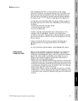
When displaying total (TOT) or inventory (INV) screens, display
resolution is 10 places, including the decimal point. The position of the
decimal point is fixed, and depends on the flow calibration factor and
units of measure. If totalizers exceed the maximum display capability,
the display reads "*********". Clear the message with the Reset knob.
If a message exists, the blinking "Msg" (message) indicator appears in
the bottom right corner of each screen, indicating any of the following
conditions:
• Power to the transmitter has been cycled.
• The flowmeter has been zeroed.
• An error condition exists.
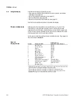
To read a message, scroll past all process variable screens to the
message screen (see Table 6-1, page 60). Uncorrected status
conditions remain in the message queue. Other messages are cleared
when the Scroll button is used to scroll past the message screen to the
flow rate screen.
If power to the transmitter has been cycled and the transmitter is
operating properly, the message reads "Sensor OK *POWER /
RESET*".
For more information about messages, refer to Section 7.4, page 73.
Communication
configuration mode
Switch 5 on the transmitter control board allows the user to select the
standard communication configuration or establish a user-defined
configuration. See Section 2.3, page 5, and "Communication settings",
page 9. The communication configuration mode allows the user to
configure the transmitter's digital communication output using the
display and the Scroll and Reset buttons.
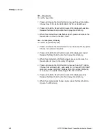
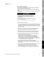
• If switch 5 is in the USER-DEFINED position, enter the communication
configuration mode from any process variable screen by pressing and
holding the Scroll button and the Reset button at the same time. In the
communication configuration mode, the text "M1", "M2", and "M3" will
appear in the upper left corner of the screen.
• For RFT9739 software versions 3.6 and later, if switch 5 is in the STD
COM position, an error message will be displayed if an attempt is made
to change the communication configuration using the Scroll and Reset
buttons.
Содержание Fisher Rosemount RFT9739
Страница 1: ...Model RFT9739 Rack Mount Transmitter Instruction Manual Version 3 Transmitters February 2000 ...
Страница 2: ......
Страница 4: ......
Страница 20: ...10 RFT9739 Rack Mount Transmitter Instruction Manual ...
Страница 26: ...16 RFT9739 Rack Mount Transmitter Instruction Manual ...
Страница 92: ...82 RFT9739 Rack Mount Transmitter Instruction Manual ...
Страница 100: ...90 RFT9739 Rack Mount Transmitter Instruction Manual ...
Страница 110: ...100 RFT9739 Rack Mount Transmitter Instruction Manual ...
Страница 112: ...102 RFT9739 Rack Mount Transmitter Instruction Manual ...
Страница 120: ...110 RFT9739 Rack Mount Transmitter Instruction Manual ...
Страница 122: ...112 RFT9739 Rack Mount Transmitter Instruction Manual ...
Страница 129: ......

