Output Wiring
continued
RFT9739 Rack-Mount Transmitter Instruction Manual
39
O
u
tp
ut Wi
ri
ng
Star
tu
p
T
ro
u
b
le
s
hoo
ting
Be
fo
re
Y
o
u
B
e
g
in
Getti
ng Sta
rted
M
oun
ting
P
o
w
e
r-
Suppl
y and
Sen
s
or Wi
ri
ng
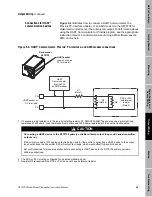
Optocoupler output
The transmitter has an externally powered passive optocoupler output in
addition to the frequency/pulse and dual-channel frequency outputs.
The optocoupler output is derived from the primary frequency output,
and represents the same flow rate variable as the frequency/pulse
output.
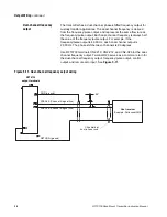
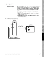
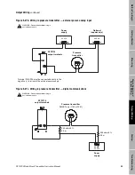
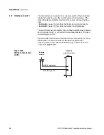
Use RFT9739 terminals CN2-D10, CN2-D12, and CN2-D4 for the
optocoupler output.
• Figure 5-15 illustrates the wiring connection from the optocoupler
output to an auxiliary device.
• Signal voltage is 0-2 VDC low, 16-30 VDC high, with a 0.01 ampere
maximum sinking capability.
Figure 5-15. Optocoupler output wiring
Clip shield at
host receiver end
OPTOCOUPLER– (emitter)
GND (ground)
RFT9739
output terminals
OPTO (collector)
Host receiver
Example: PLC
Содержание Fisher Rosemount RFT9739
Страница 1: ...Model RFT9739 Rack Mount Transmitter Instruction Manual Version 3 Transmitters February 2000 ...
Страница 2: ......
Страница 4: ......
Страница 20: ...10 RFT9739 Rack Mount Transmitter Instruction Manual ...
Страница 26: ...16 RFT9739 Rack Mount Transmitter Instruction Manual ...
Страница 92: ...82 RFT9739 Rack Mount Transmitter Instruction Manual ...
Страница 100: ...90 RFT9739 Rack Mount Transmitter Instruction Manual ...
Страница 110: ...100 RFT9739 Rack Mount Transmitter Instruction Manual ...
Страница 112: ...102 RFT9739 Rack Mount Transmitter Instruction Manual ...
Страница 120: ...110 RFT9739 Rack Mount Transmitter Instruction Manual ...
Страница 122: ...112 RFT9739 Rack Mount Transmitter Instruction Manual ...
Страница 129: ......

