3
©2021 Micro-Air Corp
August 2, 2021, revision 1.4
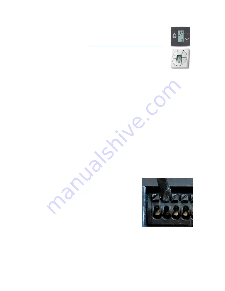
The EasyTouch 351 model thermostat was designed to replace certain
Dometic
™
single-zone thermostats. Original thermostats replaced by this model are a
square design with a center LCD display and three buttons. If your thermostat is not
of this style, please contact Micro-Air
https://www.micro-air.com/SupportRequest
to verify the thermostat you received is correct for your application.
Installing the thermostat
There are three steps to installing the thermostat. First remove your old
thermostat. Next disconnect and reconnect the wiring. Finally install the mounting pins to the wall and
mount your new thermostat.
Removing the old thermostat
We recommend you disconnect the DC power from the thermostat circuit in your RV. The power
wires are live and shorting them together could blow a fuse somewhere in the RV. Since these locations
are not well documented, removing power prevents having to find them.
There are two basic styles of three button thermostat. The first has a + and
–
button to change
temperature and on/off/mode button on the bottom with a small square display in the center. To
remove this style, depress the rectangular locking tab on the bottom of the thermostat with a small
screw driver. Pull the thermostat away from the wall from the bottom.
The second style has up and down arrows to change temperature, a rectangular LCD display and
a power/mode button. Carefully hold the base of the thermostat at the bottom while pulling the cover
plate away from the wall. It is easiest to pull at one of the corners to get the plastic to pop off.
Before removing the wiring, write down the color of the wire and the terminal each wire goes
to. Wires will be l12V, COM or COMMS, and -12V or GND. disconnect the wiring and remove
any wall attachment screws. Remove the back plate from the wall.
Using the push button terminals
Figure 1 shows a screwdriver depressing the push button
connector. The silver gate is opened for the wire to be inserted.
Releasing the button traps the wire and makes the connection.
Remove approximately 3/8 inch (1cm) of insulation from
the wire to be inserted. Use a small screw driver (not provided) or
similar tool to push down on the square push button. Insert the
wire in the insertion space and release the push button. Verify the
connection by gently pulling on the wire. Do not force excessive
wire down into the connector. If the stripped wire end is longer
than 3/8 inch, cut the end so there is no bare wire sticking out when
properly inserted.
Figure 2
Figure 1


