5
SY87729/39L
Evaluation Board
Micrel, Inc.
M9999-071906
[email protected] or (408) 955-1690
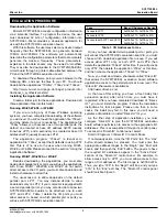
Click the “OK” button. Check your work by running the
“739ev” application. If, instead of running, you get a message
box like that in Figure 9, you’ve performed one or more of
the above steps incorrectly. Re-read this section carefully,
and try again.
Figure 9. Error Message if “Direct-IO”
Incorrectly Installed
Using the Application Software
The application software consists of two components, a
calculation module “739ifier”, and a download module,
“739ev.” There can be only one instance of the download
module running at any given time, but there can be any
number of instances of the calculation module running,
easing testing at multiple frequencies.
Using the Calculation Module:
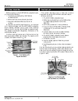
The parts of the calculation module appear in Figure 10
below.
SY87739L
Parameters
Show Up
Here
This Button
Puts
Parameters
in the
Download
Program
Choose
Wrapper
Reservation
Here
Reference Frequency
Goes Here
Actual
Frequency
Out Displays
Here
Desired Output
Frequency
Goes Here
Status Shows
Up Here
Figure 10. The Calculation Module
The purpose of the calculation module is to ease the
burden on the designer using SY87729/39L. Instead of
manually figuring out the configuration values, the calculation
module will determine the optimal configuration parameters,
based on three inputs.
The calculation module accepts these three inputs, and
displays several outputs. The first input accepted is the
reference frequency of the clock being provided to the
SY87729/39L. This goes in the “Reference” edit box. When
starting an instance of the calculation module, this edit box
is preset to 27MHz, the frequency Micrel recommends when
synthesizing clocks for standard protocols. This also happens
to be the frequency of the on-board reference oscillator
provided with the SY87729/39L evaluation board. Should
the user wish to use a different reference frequency, type it
in here.
A note on entering data in the “Reference” or “739 Output”
edit boxes. To ease typing, you may use the suffix “m” or
“k” for “mega” or “kilo” respectively. For example, to type in
27MHz, you can strike the following keys: “2”, “7”, and “m”.
The second input is the user’s decision whether or not to
reserve the wrapper synthesizer on the SY87729/39L. In
most circumstances, the wrapper synthesizer should be
used. That is why the calculation module starts with the
“Use” radio button selected in the “Wrapper” group box.
This tells the calculation module to use the wrapper
synthesizer, if there is some advantage in doing so, to
generate the target output frequency.
On the other hand, to reserve the wrapper synthesizer,
click on the “Reserve” radio button in the “Wrapper” group
box. This tells the calculation module to not use the wrapper
synthesizer when generating output frequencies. The “M”
and “N” parameters will always be 14, indicating that the
wrapper synthesizer is not modifying the output of the
fractional-N synthesizer.
As shown later in this document, using the wrapper
synthesizer generally results in a better output frequency,
smaller frequency error, and lower jitter. An example where
the user might wish to reserve (not use) the wrapper
synthesizer is in an application where not only several data
rates may need to be accepted, but also these data rates
may or may not optionally be modified with some FEC or
digital wrapper. Perhaps a DWDM input would need to
accept a list of possible inputs. But, these may have no
FEC, an ITU standard FEC, or a proprietary digital wrapper
for each input data rate.
One technique would be to create an initial list of data
rates to accept, and from these, a list of desired reference
clocks the SY87729/39L would need to generate. From this
list, generate a list triple in size. From this new, larger list,
type in each frequency and record the SY87729/39L
configuration parameters that would generate these.
An alternative would be to reserve the wrapper
synthesizer, and then to form a list of configuration
parameters for just the base frequencies. The user would
then modify just the “M” and “N” parameters to allow without
FEC, with FEC, or with digital wrapper.
The third input is the desired output frequency. Please
keep in mind that the output frequency range is from 9MHz
to 729MHz. Like the input frequency, you can use suffixes.
As an example, let’s synthesize 8,900,000Hz from a 27MHz
input. Launch “739ifier”. The input frequency is already set
to 27MHz, the wrapper is already set to be used, and the
cursor is ready to accept an output frequency. Type “8”, “.”,
“9”, and “m”. You will get a beep. The status line, the line
just below the output frequency, begins with the word
FAILED, like in Figure 11. It is VERY IMPORTANT to note
that NONE of the SY87729/39L parameters, even if
displayed, is valid when the status line begins with either
the word FAILED or the word STALE.


