background image

XZR200 User’s Manual

6


97337 Issue 4, July 2018

INSTALLATION

3 INSTALLATION

!

When installing the sensor do not use any lubricants or grease 

which may contain silicone.


!

The sensor is located in the tip of the probe and is heated to 

700°C (1292°F). 

Do NOT touch the probe tip with bare hands as this will cause 

damage to skin. 

3.1 

Mounting and Orientation

!

The XZR200 should be grounded (earthed) via the probe as well 

as through the cable.


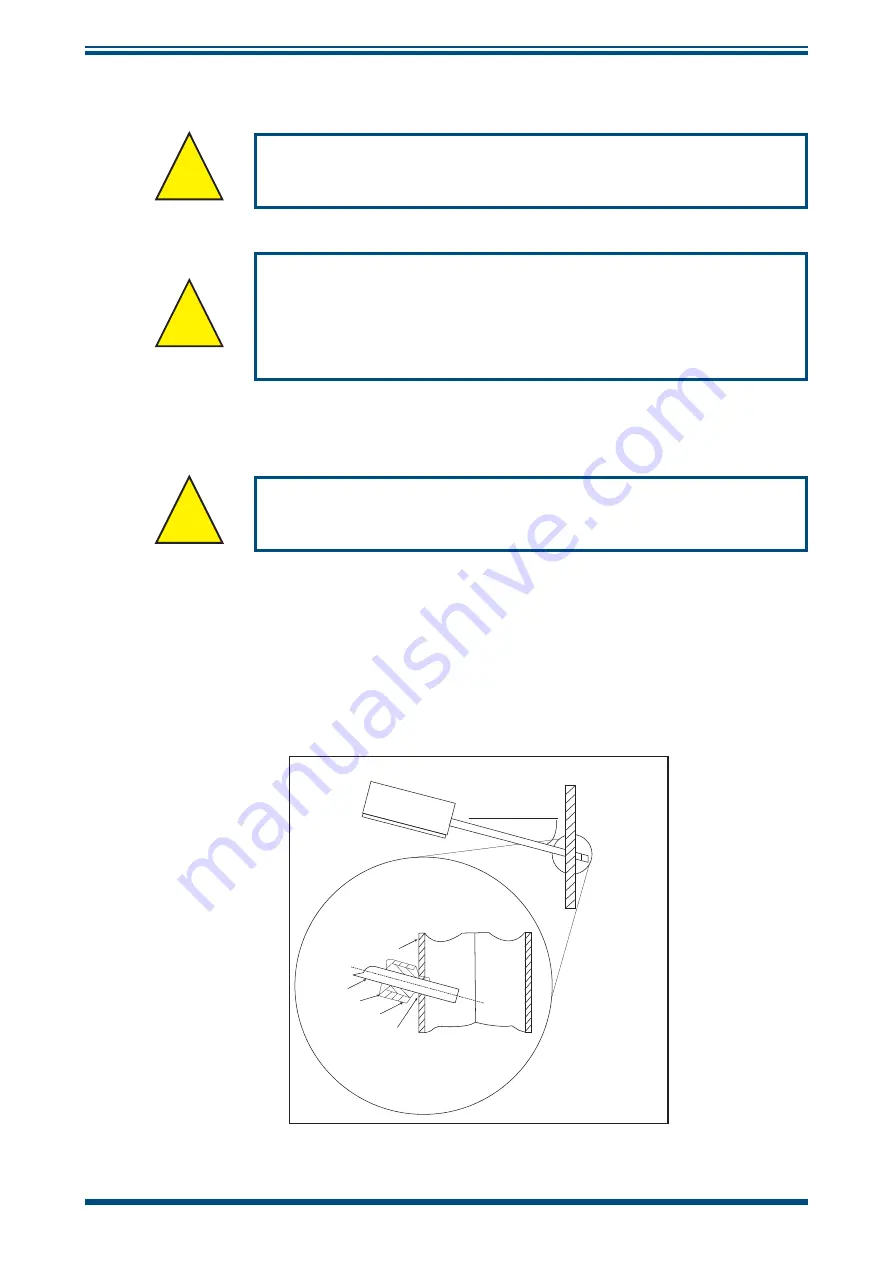
When using the XZR200 in a combustion process the diagram below shows the correct 

mounting and orientation. The downward angle of the probe tip will protect the sensor 

from dust settling or moisture sitting in the tip and damaging the sensor.

A 12mm 

fi

 tting with a retaining nut that can be welded to the process and 

fi

 x the probe 

in position. A suitable O-ring should be used to ensure a good seal.

Housing

15°

Partition

Bar Probe

O-Ring

Nut

Weld Socket

Partition

Atmospheric Air

+60°C Max

Gas Mixture

+250°C Max

+400°C Max

Figure 3 

Mounting and Orientation

Содержание XZR200

Страница 1: ...XZR200 Oxygen Analyzer User s Manual 97337 Issue 4 July 2018 ...

Страница 2: ...information when contacting Michell Instruments for service purposes Instrument Code Serial Number Invoice Date Location of Instrument Tag No Instrument Code Serial Number Invoice Date Location of Instrument Tag No Instrument Code Serial Number Invoice Date Location of Instrument Tag No ...

Страница 3: ...Ltd and may not be copied or otherwise reproduced communicated in any way to third parties nor stored in any Data Processing System without the express written authorization of Michell Instruments Ltd XZR200 For Michell Instruments contact information please go to www michell com ...

Страница 4: ... Block Diagram 8 3 4 RS232 Communication Settings 8 3 5 RS232 Operation 9 3 6 RS232 User Configurable Options 9 3 6 1 Menu Screens 9 3 6 2 Changing the Menu Access Password 9 3 6 3 Variable Output Filtering Td Averaging 10 3 6 4 Changing the Automatic Calibration Value 10 3 6 5 Adjusting the Minimum and Maximum Ranges of the Analog Outputs 11 3 7 Continuous Data Streaming 12 4 CALIBRATION 13 4 1 A...

Страница 5: ...tion 4 Figure 3 Mounting and Orientation 6 Figure 4 Electrical Connections 7 Figure 5 System Block Diagram 8 Figure 6 COM Port Settings 8 Figure 7 Sensor Damage 14 Appendices Appendix A Technical Specifications 18 Appendix B Theory of Operation 21 Appendix C Quality Recycling Warranty Information 25 Appendix D Analyzer Return Document Decontamination Declaration 27 ...

Страница 6: ...pressures However it is possible to measure in the range 0 to 25 O2 at pressures up to 5 barg 72 5 psig without damage to the unit The unit will require calibration at the operating pressure and a separate pressure transducer feeding into your control system may also be required Toxic Materials The use of hazardous materials in the construction of this instrument has been minimized During normal o...

Страница 7: ...standard cubic feet per hour Td cycle time to evacuate and re pressurize the sealed cell Td averaging counting x number of cycles and averaging the result V Volts percentage inches Warnings The following general warning listed below is applicable to this instrument It is repeated in the text in the appropriate locations Where this hazard warning symbol appears in the following sections it is used ...

Страница 8: ...and notifications Note Warnings and items of importance will be marked with bold text 1 1 Features Accurate linear configurable outputs 4 20mA 0 10 V DC or RS232 Selectable output measurement ranges Standard ranges of 0 to 25 O2 and 0 to 100 O2 or fully adjustable via RS232 when configured in 0 to 100 O2 mode Externally triggered automatic or manual calibration Calibrated in ambient air 20 7 O2 or...

Страница 9: ...rements change by simply altering the position of jumper links on the PCB The electronics are housed in an IP65 die cast aluminum housing The oxygen sensor is mounted in the tip of the stainless steel probe and is protected by a stainless steel sintered cap which acts as both a large particulate filter and also as a flame trap A digital 3 3 V DC logic output cycles at the same frequency as the ele...

Страница 10: ...result in product damage Products damaged due to incorrect configurations will not be covered under warranty 1 Power down the analyzer 2 Remove the lid using a Phillips cross head screwdriver 3 Adjust the position of the jumper links to the desired configuration Thin nosed pliers should be used to remove and replace the jumper links Ensure the jumper links are correctly seated before reapplying th...

Страница 11: ...ive due to thermal oxidation Regular calibration removes the effect of initial sensor drift as the sensor output is constantly re referenced against the known calibration gas However if regular calibration is not possible and the output is required to have stabilized prior to use in the application then it may be necessary to actively burn in the sensor Active burn in involves operating the sensor...

Страница 12: ... the XZR200 sensor will have a variable lifespan In ambient temperatures with inert gases the sensor should last approximately 7 years For combustion processes the following guide should be used Natural gas Approximately 5 to 7 years Biogas Approximately 3 to 4 years Biomass Approximately 2 years Coal and Oil Approximately 1 to 2 years If there is zero oxygen in the sample the sensor will still tr...

Страница 13: ... the probe as well as through the cable When using the XZR200 in a combustion process the diagram below shows the correct mounting and orientation The downward angle of the probe tip will protect the sensor from dust settling or moisture sitting in the tip and damaging the sensor A 12mm fitting with a retaining nut that can be welded to the process and fix the probe in position A suitable O ring s...

Страница 14: ...GND 0 V DC 8 NC Connector Body Housing Probe Earth 1 2 6 5 4 3 7 8 NOTE The above view of the electrical connections is shown from the mating side Here are the connections as viewed from the back of the connector and this should be used for wiring purposes Figure 4 Electrical Connections Housing connector 99 3481 578 08 Mating connector 713 99 1486 812 08 mating connector supplied loose with each ...

Страница 15: ... 24 V DC Pin 1 100 to 600Ω GND Pin 7 24 V DC POWER SUPPLY Figure 5 System Block Diagram 3 4 RS232 Communication Settings When connecting the XZR200 via the RS232 connections ensure Tx goes to Rx of the PC and Rx goes to Tx of the PC The XZR200 communicates via standard COM port settings that are default on most PC s and many other RS232 compatible devices If however communication problems are occu...

Страница 16: ...or diagnostics and information although there are user configurable options that may be changed These are the amount of output filtering averaging the automatic O2 calibration and the analog output ranges All three processes are further described below The menu access password may also be changed by the user as shown below 3 6 2 Changing the Menu Access Password The password is factory set to defa...

Страница 17: ...l value of Td per mbar of PPO2 is 1 05ms 15 For example if we have 20 7 oxygen in 1000mbar barometric pressure the PPO2 value would be 207mbar This equates to a typical Td of 207 1 05 217 5ms To convert the XZR200 Td output back to ms the number must be multiplied by 0 000048 which is the clock period of the microprocessor in seconds So for the example above a Td value of 217 5ms would be output f...

Страница 18: ...hen enter your security password Press ENTER to access the menu screen 4 In the Configuration Menu menu 2 enter the maximum range screen Option 3 Enter O2 Max Range 5 The number entered should be between 1 00 and 100 00 to represent the maximum output range The number must also be greater than the saved minimum range 6 Press ENTER to save and ESC to return to the Configuration Menu 7 Enter the min...

Страница 19: ...measurement gas The O2 concentration is the Td value scaled by the stored calibration value The averaged values give a stable smooth output while the raw un averaged values allow the user to detect sudden oxygen changes The averaged value is the measurement output on both the 4 20mA and 0 to 10 V DC outputs The user can alter the averaging setting to suit the application requirements NOTE To stop ...

Страница 20: ...N 6 for a minimum of 12 seconds During the 12 seconds the CYCLE output PIN 7 and the green LED will go high on blink rapidly go high on go low off then return to cycling normally to indicate normal operation has resumed At this point remove GND from PIN 6 4 The output will now track to the correct value for the calibration gas Calibration is complete Calibration values are retained on power loss 4...

Страница 21: ...long sensor life 5 2 1 Operating the Sensor in Aggressive Humid Environments When operating the sensor in warm humid environments it is important the sensor remains at a higher temperature than its surroundings especially if there are corrosive components in the measurement gas During operation this is not a problem due to the 700 C 1292 F generated by the heater However when the sensor or applica...

Страница 22: ...ailable The sensor will measure the residual oxygen pressure which leads to a measurement error low oxygen reading The sensor is not recommended for use in applications where there are large amounts of combustible gases present and an accurate O2 measurement is required Gases tested H2 Hydrogen up to 2 stoichiometric combustion CO Carbon Monoxide up to 2 stoichiometric combustion CH4 Methane up to...

Страница 23: ... 4 Using the Sensor with Silicones The XZR200 oxygen sensor like all other Zirconium Dioxide sensors will be damaged by silicon presence in the measurement gas Vapors organic silicone compounds of RTV rubbers and sealants are widely used in many applications These materials which are often applied as a liquid or gel still release silicone vapors into the surrounding atmosphere even after they have...

Страница 24: ...XZR200 User s Manual Michell Instruments 17 CALIBRATION Appendix A Technical Specifications ...

Страница 25: ...to 25 or 0 to 100 Digital Communications RS232 not available if 4 20 mA output selected Operating Conditions Ambient Temperature 10 to 85 C 14 to 185 F Mechanical Specifications Warm Up Time Approximately 10 minutes Stabilization Time Included in the above Dimensions 52 x 75 x 80mm 2 05 x 2 95 x 3 15 h x w x d excluding probe Probe Dimensions 210 or 400mm length ø 12mm 8 27 or 15 75 length ø 0 47 ...

Страница 26: ...nsions Mounting Holes ø 4 5mm ø 0 18 x 2 Mounting holes accessible on removal of housing lid Top View Side View Bottom View 80mm 3 15 210 or 400mm 8 27 or 15 75 75mm 2 95 52mm 2 05 52 4mm 2 06 62 6mm 2 46 ø 12mm ø 0 47 52mm 2 05 g g g i i i j j j h h h h h h h ...

Страница 27: ...XZR200 User s Manual 20 97337 Issue 4 July 2018 APPENDIX B Appendix B Theory of Operation ...

Страница 28: ...ssure which the single gas component would exert if it alone occupied the whole volume Dalton s Law The total pressure ptotal of a mixture of ideal gases is equal to the sum of the partial pressures pi of the individual gases in that mixture Σ k i 1 P i P total From the equation above it can be derived that the ratio of the number of particles ni of an individual gas component to the total number ...

Страница 29: ...contamination of the cell which may lead to unstable measurement readings The above figure shows a cross section of the sensing cell with all the major components highlighted A heater coil which produces the necessary 700 C 1292 F required for operation surrounds the sample cell Both are housed within a porous stainless steel cap to filter larger particles and dust The filter cap also protects the...

Страница 30: ...two reference voltages and every time either of these two references is reached the direction of the constant current source is reversed When the PPO2 is high it takes longer to reach the pump reversal voltages than it does in a low PPO2 atmosphere This is because a greater number of oxygen ions are required to be pumped in order to create the same ratio metric pressure difference across the sensi...

Страница 31: ...XZR200 User s Manual 24 97337 Issue 4 July 2018 APPENDIX C Appendix C Quality Recycling Warranty Information ...

Страница 32: ...ives Full information can be found on our website at www michell com compliance This page contains information on the following directives ATEX Directive Calibration Facilities Confl ict Minerals FCC Statement Manufacturing Quality Modern Slavery Statement Pressure Equipment Directive REACH RoHS2 WEEE2 Recycling Policy Warranty and Returns This information is also available in PDF format ...

Страница 33: ...XZR200 User s Manual 26 97337 Issue 4 July 2018 APPENDIX D Appendix D Analyzer Return Document Decontamination Declaration ...

Страница 34: ...hemicals YES NO Radioactive substances YES NO Other hazards YES NO Please provide details of any hazardous materials used with this equipment as indicated above use continuation sheet if necessary Your method of cleaning decontamination Has the equipment been cleaned and decontaminated YES NOT NECESSARY Michell Instruments will not accept instruments that have been exposed to toxins radio activity...

Страница 35: ......

Страница 36: ...http www michell com ...

Отзывы: