MHS Boilers XenoROL XR40 Скачать руководство пользователя страница 62

XenoROL® 

62


REPAIR PROCEDURES 

COUPLER CHAINS 
If the coupler failed from torque fatigue, analyze the 
amount of conveyor driven from that coupler. 
Perhaps the drive load can be shared better with 
adjoining conveyors. If the coupler failed from line-
shaft misalignment, this condition must be corrected 
before the new chain is installed. (Ref. installation 
procedures for coupler chains on page 19 & 20). If 
corrective steps are not taken to address the cause 
of breakage, the replacement coupler chain will 
probably also fail. The set screws in coupler 
sprockets must be torqued to 13 ft-lb. 

CHAIN & SPROCKETS 
Lubrication of roller chains is essential to effectively 
minimize metal-to-metal bearing contact of pin-
bushing joints in the chain. Oil should be applied to 
outside and inside plate edges, since access to the 
pin-bushing area is possible only through clearances 
between the outside plates and the inside plates. Oil 
applied on the center line of the rollers cannot reach 
pin-bushing joints. 

Chain drives should be protected against dirt and 
moisture. Oil supply should be kept free of 
contamination. A good grade of non-detergent 
petroleum base oil is recommended. Heavy oils and 
greases are generally too stiff to enter and fill the 
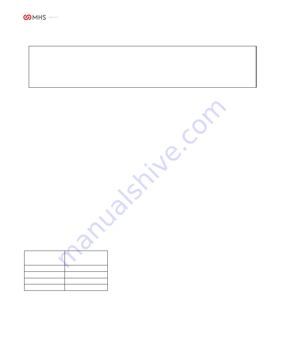
chain joints. The following table indicates the proper 
lubricant viscosity for various surrounding 
temperatures. 

Temperature 

Degrees F 

Recommended 

Lubricant  

20 TO 40 

SAE 20 

40 TO 100 

SAE 30 

100 TO 120 

SAE 40 

120 TO 140 

SAE 50 

Inspection includes: 

1.

Lubrication check for dirt, grit, or chips
and clean if necessary by soaking chain
in nonflammable cleaning solvent

2.

2. Sprocket alignment (see following
text)

3.

Wear on the inner surfaces of the roller
chain link plates

4.

Sprocket tooth wear

5.

Chain tension (see following text)

6.

Set screw tightness (5/16-18 at 13 ft.lbs.
and 1/4- 20 at 6 ft.lbs.)

SPROCKET ALIGNMENT 

1.

Loosen sprocket.

2.

Align loose sprocket to the other by
laying a straight edge across their faces
or along the chain.

3.

Retighten the loose sprocket.

CHAIN TENSION 
Chain should be checked for excessive slack, if the 
chain is running close to the tips of the sprocket 
teeth. 

This can be checked by lifting the chain away from 
the large sprocket, making sure the chain is in mesh 
with the sprocket teeth. Excess clearance is 
conclusive evidence that the chain has elongated in 
pitch and no amount of tension adjustment will keep 
it properly meshed with the sprocket teeth. 
Continued operation will quickly destroy the sprocket 
teeth which otherwise may be good. If the sprocket 
is still serviceable, replace the chain. 

TENSION ADJUSTMENT 

1.

Loosen mounting bolts of tension.

2.

Increase tension up to 1/2" of total slack
(1/4" each way of center).

3.

Turn adjusting bolts on gearbox plate or
move gearbox in mounting slots until
there is 1/2" total chain slack.

4.

Retighten all bolts after checking
alignment.

If chains have stretched so that above adjustments 
cannot be made, remove a link and reconnect. (If 
removal of one link makes the chain too short, add 
offset link and reconnect.) 

If a chain should break or fail due to overload, 
neglect or accident, those portions of the chain 
which appear to remain intact are, in all probability, 
damaged and subject to early failure if continued in 
service. Replace the entire chain and sprockets. 

WARNING 

Do not perform maintenance on the conveyor until the start-up controls are locked out and cannot 

be turned on by any person other than the one performing the maintenance. If more than one 

member of a crew is working on the conveyor, EACH CREW MEMBER MUST HAVE A LOCK ON THE 
POWER LOCK OUT. The air pressure must be turned off to the work areas. Make sure personnel are 

clear of all conveyor equipment before restarting the system. 

Do not use gasoline or kerosene for cleaning. Use nonflammable solvent only.


90480006rev092010 

Содержание XenoROL XR40

Страница 1: ...XenoROL 1 INSTALLATION OPERATION MAINTENANCE MANUAL XenoROL XR40 and XR48 90480006rev092010...

Страница 2: ...GENERAL 13 PREPARATION OF SITE 13 PARTS INVENTORY IDENTIFICATION 13 TYPICAL XenoROL LOOSE PARTS 14 GENERAL PROCEDURES 15 DIMENSIONAL REFERENCE POINTS 15 ELEVATIONS 15 TYPICAL LAYOUT LEGEND 16 LAYOUT...

Страница 3: ...ODULE RAC UBT MODULE 34 XenoBRAKES 35 POWERED GATE ASSEMBLY 36 ROLLERS 37 STRAIGHT ROLLERS 37 TAPERED ROLLERS 37 ROLLER INSTALLATION 37 LINE SHAFT GUARDS 38 GUARDS FOR INCLINED STRAIGHT SECTIONS 38 GU...

Страница 4: ...uide 52 TROUBLESHOOTING GUIDE MECHANICAL 54 TROUBLESHOOTING GUIDE MECHANICAL 54 TROUBLESHOOTING GUIDE MECHANICAL 55 TROUBLESHOOTING GUIDE MECHANICAL 57 TROUBLESHOOTING GUIDE MOTOR REDUCER 58 TROUBLESH...

Страница 5: ...73 PARTS IDENTIFICATION 74 PARTS IDENTIFICATION 75 PARTS IDENTIFICATION 76 PARTS IDENTIFICATION 77 PARTS IDENTIFICATION LIST 78 PARTS IDENTIFICATION LIST 79 ADDITIONAL REPLACEMENT PARTS 80 XR40 48 DR...

Страница 6: ...describes basic installation practices assembly arrangements preventive maintenance repair procedures troubleshooting service internals and assists in replacement parts identification If additional c...

Страница 7: ...onditioned upon the equipment being installed handled operated and maintained in accordance with the written instructions provided or approved in writing by MHS Conveyor The warranties specified above...

Страница 8: ...deface or paint over WARNING or CAUTION labels Any damaged label will be replaced by MHS Conveyor at no cost by contacting the Customer Service Department It is very important to instruct personnel i...

Страница 9: ...XenoROL 9 90480006rev092010...

Страница 10: ...ibutes to the horsepower requirement of the line shaft Accumulation Minimum Pressure Act of queuing holding or backing up of product on a conveyor Carrying Roller The conveyor roller upon which the ob...

Страница 11: ...aft Guard Provided to prevent entanglement in rotating parts Roller Centers Distance between center lines of adjacent rollers For curves roller centers are measured at the inside radius Roller Groove...

Страница 12: ...than XR40 roller drive capacity The 9 deep frame has more capacity when supported on 9 centers than XR40 or XR48 roller drive capacity MINIMUM PRESSURE ACCUMULATION When conveyed product is stopped th...

Страница 13: ...n necessary to give the area along the system path a general cleanup to improve installation efficiency access and accuracy Ceiling hung conveyor header steel should be installed well ahead of the con...

Страница 14: ...plice Angle Support Rail to Rail Joint See Page 34 95000027 1 4 20 Bolt x 2 Hex Head Upper Bracket to Channel G R See Page 34 95000075 3 8 16 x 1 Hex Head Bolt Lower Bracket to Frame and Brackets to A...

Страница 15: ...yor system proceeds onto another floor or into another building or room a new elevation will be measured from the floor at that point This new elevation will then become the reference for subsequent e...

Страница 16: ...orsepower and speed should be noted on the layout Also shown symbolically are positions of line shafts jump chains zero pressure zones transfer flow direction etc TYPICAL LAYOUT LEGEND Illustrated bel...

Страница 17: ...s into account they are most useful in making future changes to the system Note These dimensions do not include the wheel diverter Ref page 26 30 SPUR DIMENSIONS In Inches A B C D E F G H I J 15 1 2 7...

Страница 18: ...LAYOUT DIMENSIONS Never leave unused sprockets on line shaft At joint between adjacent drive units remove sprockets and add white plastic safety caps When continuing drive install coupler chain per i...

Страница 19: ...e outside channel Over 18 width should have full support ANCHORING Anchoring in concrete floors is accomplished by drilling into the floor and inserting the suitable anchor bolt The hole diameter and...

Страница 20: ...channel connector kit consists of two formed channels 4 1 2 deep with mounting hardware This connector is a standard component of ceiling hangers but is also used to allow a support on the frame join...

Страница 21: ...V brackets flat strap connectors and bed connector to one end of a bed section Hoist the bed section between the drop rods guiding the rods through the mounting holes in the cross pipe Thread the weld...

Страница 22: ...to natural side to side movement of line shaft conveyor a diagonal sway brace has been designed to reduce side movement in the standard floor support Side movement is most prevalent in long straight...

Страница 23: ...building steel Stringers when used between headers may be welded or bolted to the headers directly or with suitable angle clips Concrete Ceilings Accomplish anchoring by drilling into the concrete cei...

Страница 24: ...ments will be the same within 1 16 FRAME ALIGNMENT Conveyor frames must always be installed in a straight line from end to end as described in GENERAL PROCEDURES After a number of sections have been i...

Страница 25: ...The chain link can be supported by using a channel lock adjustable pliers and squeezing the pin in This also requires less clearance than using a small hammer and tapping the pin in Carefully note fro...

Страница 26: ...last coupler chain No drive may be located between a pair of U joints unless they are constant velocity No jump chain other than 1 1 ratio may be located between a pair of standard U joints INCLINING...

Страница 27: ...profile drive CURVES Curves are installed the same as straight sections In addition to end supports 90 degree curves should have a support in the center of the outside frame channel Curve center leg s...

Страница 28: ...ction as in a loop the belt twist on one conveyor will have to be reversed with a counterclockwise twist Internal Jump Chain Assembly The internal jump chain is offered in 10 and 2 long beds The 10 lo...

Страница 29: ...ive capacity due to the larger diameter belt it is recommended that the spur be mounted 1 4 higher than the rollers in the abutting bed to delay the pull of the abutting bed until the product is drive...

Страница 30: ...g size products to prevent them from getting side by side if a backup occurs against one arm Tip Light products will push through the arms easier if skewed away from the traffic controller toward the...

Страница 31: ...rival at the diverter All products must divert to the same side and must be aligned along the spur side ahead of the diverter Conveying surface must be flat and firm with very little distortion under...

Страница 32: ...elt Bi Directional UBTs allow product to be transferred or received from either side of the conveyor with 1 4 dia belts Line shaft rotation can be either direction Two transfer belt lifting tables con...

Страница 33: ...SI Maximum product weight should not exceed 80 lbs at 60 FPM Accumulation held by the stop should not exceed 30 Pivoting roller stops are normally received preassembled separate from the bed they are...

Страница 34: ...e right angle gearbox and its adjoining bed This adjoining conveyor should be supported within 2 0 of this connection The UBT frame is supported at each end Since this frame is 9 deep follow the conne...

Страница 35: ...ired this may be increased to a maximum of 80 PSI Normally XenoBRAKES are factory mounted in the conveyor bed however they may be purchased separately and mounted during installation A brake is preass...

Страница 36: ...eam Right hand is the opposite with the shaft on the right hand SUPPORTING 1 Mount a floor support under these channels Install the two striker channels under the conveyor bed following the gate so th...

Страница 37: ...ll widths ROLLER INSTALLATION Twist all belts in the same direction The twist of the belt determines the direction of the roller rotation and conveyor travel When devices such as urethane belt transfe...

Страница 38: ...ation GUARDS FOR INCLINED STRAIGHT SECTIONS Line shaft conveyors are often inclined or declined through the use of constant velocity universal joints at the upper and lower transition points The line...

Страница 39: ...oles do not align clamp the guard rail in place and drill new holes 3 Bolt the guard rail to the curve with the appropriate number of truss head bolts ADJUSTABLE CHANNEL GUARD RAIL Adjustable channel...

Страница 40: ...main feeder line MAIN FEEDER Air velocity through the main feeder piping can be kept smooth with lower losses using large diameter pipe with minimum bends and restrictions The main feeder carries the...

Страница 41: ...allows the operator to verify that no one is on the conveyor or would be in danger if the conveyor were to start up If all conveyors being started cannot be seen from the start pushbutton location the...

Страница 42: ...gency stops may be located throughout a system such that it is possible to shut down the system The location will depend on likely observation points and areas with special devices and interfaces betw...

Страница 43: ...t timing functions Adjust limit switches Verify circuitry Verify proper line voltage Verify function of all safety shutoff devices Verify sequence of operation Verify each motor has lockable disconnec...

Страница 44: ...re and on the motor shaft CHAINS AND SPROCKETS Chains and sprockets should be checked monthly Look for correct alignment In time set screws may loosen and allow the sprockets to become misaligned Use...

Страница 45: ...amount due to seating of pins and bushings during the first 250 hours of operation Chains on drives having near vertical centers should be kept reasonably tight with idler sprockets TIMMING BELT PULLE...

Страница 46: ...nsioning the timing belt Following these methods will properly tension the belt If after tensioning you have problems with the timing belt jumping teeth you need to look for problems that can cause ex...

Страница 47: ...2 46 23 32 60 15 16 19 19 64 33 33 64 47 47 64 61 61 64 For Drives use a Tension Force of 4 lb lb For Jumps use a Tension Force of 2 lb lb For MOVIMOT drives use a Tension Force of 1 lb lb ROLLERS For...

Страница 48: ...ntrol cabinet it is best to use a vacuum cleaner rather than compressed air A vacuum cleaner removes rather than redistributes dust and dirt Compressed air can damage and displace relay contacts and s...

Страница 49: ...the system and correct promptly Check all air line filter bowls for accumulated water and drain if necessary Check for proper PSI settings on air regulators Monitor bowl drain every week To manually...

Страница 50: ...oil level in gearcase if applicable unusual noises vibration and stress cracks Check drive belts for wear cracks or breaks Lubricate U joints SEMI YEARLY If dry sounding lubricate unsealed bearings in...

Страница 51: ...ons See Page 39 54 Mobil DTE Extra Heavy Oil 936133160 Guide Posts Lift Table Urethane Belt Transfer See Page 41 Light Oil Rollers Product support and driving rollers See Page 40 Light Machine Oil Air...

Страница 52: ...ing troubleshooting guide lists certain conveyor problems possible causes and corrections These procedures will help in identifying and correcting these problems Problems may have several possible cau...

Страница 53: ...ace roller 4 Broken belt Belt rubbing on interference Make clearance then replace belt Age Flex life Replace belt 5 Weak belts Reaction to chemical Correct cause Excessive temperature Replace with hig...

Страница 54: ...mber too short Shim crossmember at frame Frame bent Straighten frame or replace Roller too long Replace roller with shorter one 14 Excessive sprocket wear Loose chain Tighten chain Ref p 52 Misalignme...

Страница 55: ...nment of chain guard Align sprockets and chain guard Overload Adjust guard as appropriate Inspect for obstruction to or drag on conveyor 22 Broken chain Drive overload Avoid overloading Reduce unit le...

Страница 56: ...XenoROL 56 90480006rev092010...

Страница 57: ...ttom surface of the rollers and bottom mounting bolts in the frame holes See Note 1 29 XenoBRAKE not stopping rollers Alignment to the rollers See 28 above Inadequate air pressure or supply See Note 1...

Страница 58: ...d panel Motor wiring Check heater size and amp draw Check motor wiring Drag on conveyor Check all bearings 34 Drive slow to start Electrical Check circuits and panel Take ampere reading 35 Motor will...

Страница 59: ...XenoROL 59 Input shaft key missing or defective Replace key 90480006rev092010...

Страница 60: ...ing out Incorrect size Check overload size and replace if necessary Short in motor Replace motor 39 Motor runs line shaft does not turn Drive chain broken or disconnected Replace chain Ref p 52 Sprock...

Страница 61: ...See Solenoid Valves Ref p 56 Faulty valve to base gasket Faulty seals Damaged spool Cylinder leaks Inadequate air supply Water or oil contamination 44 Solenoid fails to actuate valve Loose pilot cover...

Страница 62: ...s and 1 4 20 at 6 ft lbs SPROCKET ALIGNMENT 1 Loosen sprocket 2 Align loose sprocket to the other by laying a straight edge across their faces or along the chain 3 Retighten the loose sprocket CHAIN T...

Страница 63: ...removal of dirt particles and other contaminants that may find their way into the bearings and indicates that the bearings are fully lubricated In addition this provides additional protection against...

Страница 64: ...oil change ordinarily experienced with conventional reducers has been eliminated With Reliance Relialube reducers change oil only when performing maintenance that requires gearbox disassembly In this...

Страница 65: ...3 RIGHT ANGLE CONNECTION Service life and efficiency of gears and bearings will be affected by oxidation or contamination of the lubricating oil Improved performance will be obtained by periodic relub...

Страница 66: ...ck using the following procedure Preheat the iron with the adjustment knob at approximately the three fourths setting for a couple of minutes Feed new length of belt around line shaft Holding one end...

Страница 67: ...hich defective valve is mounted Remove solenoid wires from their terminals Loosen and remove two Allen head screws on top of valve body Remove valve and gasket from subbase Install replacement valve a...

Страница 68: ...Check for loose wiring and tighten as required CLEANING When cleaning a control cabinet it is best to use a vacuum cleaner rather than compressed air A vacuum cleaner removes rather than redistributi...

Страница 69: ...received It includes part numbers description pricing and recommended quantities to be kept for maintenance If you are unable to locate this document orders under 5 000 another may be obtained by con...

Страница 70: ...XenoROL 70 PARTS IDENTIFICATION INTERMEDIATE BEDS CURVES 90480006rev092010...

Страница 71: ...XenoROL 71 PARTS IDENTIFICATION DRIVE PACKAGE AND BED LOW PROFILE DRIVE PACKAGE AND BED 90480006rev092010...

Страница 72: ...XenoROL 72 PARTS IDENTIFICATION URETHANE BELT TRANSFERS URETHANE BELT TRANSFERS OPTIONS 90480006rev092010...

Страница 73: ...XenoROL 73 PARTS IDENTIFICATION JUMP CHAIN ASSEMBLY RIGHT ANGLE CONNECTION URETHANE BELT TRANSFER MODULE 90480006rev092010...

Страница 74: ...XenoROL 74 PARTS IDENTIFICATION WHEEL DIVERTER ASSEMBLY MERGE ASSEMBLY 90480006rev092010...

Страница 75: ...XenoROL 75 PARTS IDENTIFICATION GATE XENOSWITCH ASSEMBLY 90480006rev092010...

Страница 76: ...XenoROL 76 PARTS IDENTIFICATION XENOBRAKE LOCATING STOP AND PIVOTING ROLLER STOP 90480006rev092010...

Страница 77: ...0224001 30 OAW 28 BF E0009799 40230001 36 OAW 34 BF E0009800 40236001 42 OAW 40 BF E0009801 40242001 XR48 Roller Assembly True Tapered Straight 18 1 2 OAW 16 BF E0009797 48218001 24 1 2 OAW 22 BF E000...

Страница 78: ...number of teeth and sprocket number 18 Sprocket XenoSWITCH Assembly 90800524 19 Sprocket XenoSWITCH Assembly 90800548 20 Sprocket Drive Refer to Drive Data page 71 21 Sprocket Driven 22 Motor 23 Redu...

Страница 79: ...Cylinder Roller Stop 89000056 48 Drive Belt Wheel Diverter 90530094 49 Wheel Sorter 90930103 50 Air Cylinder Wheel Diverter 89000122 51 Bearing 1 bore Wheel Diverter 90050223 52 Air Cylinder XenoSWITC...

Страница 80: ...9000581 Black 89000582 Drive Belt Repair Kit Including Carrying case cut length chart heating iron and 25 of drive belt cord specify diameter 99940002 Quick Replacement Belts Including S hook for stra...

Страница 81: ...3 16 9 90530003 Drive Pulley to UBT Roller 5 7 32 12 7 8 90560016 Drive Pulley to Tapered Roller 5 3 16 7 32 12 11 16 90560018 Tapered Roller to Tapered Roller 3 3 16 9 90530003 2 3 8 3 16 7 7 8 90530...

Страница 82: ...8 2 140 262 10 1 1 8 1 2 3 4 1 1 1 2 70 56 175 10 5019 7 8 2 140 262 10 1 1 8 1 2 3 4 1 1 1 2 75 56 175 10 5020 7 8 2 140 262 10 1 1 8 1 2 3 4 1 1 1 2 80 56 175 10 5018 7 8 5015 2 140 262 10 1 1 8 1 2...

Страница 83: ...17 1 1 SK272VL 80L 4 123 H5017 1 60 1 2 SK272VL 71L 4 174 H5017 1 5018 1 3 4 SK272VL 80S 4 173 H5017 1 1 SK272VL 80L 4 167 H5017 1 75 1 2 SK272VL 71L 4 226 H5016 1 5018 1 3 4 SK272VL 80S 4 224 H5016 1...

Страница 84: ...otes safety and personal development MHS Conveyor 1300 E Mount Garfield Road Norton Shores MI 49441 6097 USA 231 798 4547 Email us info mhs conveyor com Web Site mhs conveyor com Regional sales office...

Отзывы: