background image

MFJ-8621                                                                                             Data Radio 

13 

APPENDIX 
Technical Assistance 

If you have any problem with this unit first check the appropriate section of this manual. 
If the manual does not reference your problem or your problem is not solved by 
reading the manual, you may call 

MFJ Technical Service at 

601-323-0549

 or the 

MFJ 

Factory at 

601-323-5869

.  You will be best helped if you have your unit, manual and 

all information on your station handy so you can answer any questions the technicians 
may ask. 


You can also send questions by mail to MFJ Enterprises, INC., 300 Industrial Park 
Road, Starkville, MS 39759; by FAX to 

601-323-6551

; through Compuserve at 

76206,1763; or by email to [email protected].  Send a complete 
description of your problem, an explanation of exactly how you are using your unit, and 
a complete description of your station. 
 

Replacing the Fuse Link 

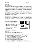
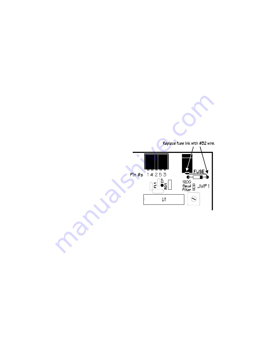
The MFJ-8621 has a thin foil trace on the pc board that acts as a line fuse.  This trace 
connects power to the rest of the circuitry and may "burn out" under certain 
conditions (such as when the MFJ-8621 is subjected to a reversed polarity power).  If 
your Data Radio does not operate and you suspect that the line fuse is broken follow 
these steps: 
 
1. Remove the cover and inspect the 

fuse line.  It may be necessary to 
test the fuse for continuity. 

 
2. If the line is broken replace it with a 

length of #32 wire of approximately 
the same length.  You may optionally 
replace the line with a heavier gauge 
of wire and protect the unit with a 2 
amp fast-blow fuse. 

 
3. Replace the cover and screws. 
 

DCD Setup 

To use the 

KPC-9612

 at 9600 baud with the MFJ-8621: 

1.  Enter the command CD SOFTWARE at the cmd: prompt. 
2.  Set the 9600 receive level jumper (J9) to "ON" (both pins shorted together). 
3.   Set the 9600 equalization header for "variable" (pin 2 shorted to center). 
4.  Set the 9600 equalization pot (R33) from approx. 11 to 12 o' clock. 
5.  Set 9600 baud drive jumper (J7) to low range (jumper one pin only). 
6.  Set the 9600 baud drive control (R32) to midrange. 
 
To use the 

KPC-3

 at 1200 baud with the MFJ-8621: 

1.  Enter the command CD SOFTWARE at the cmd: prompt. 
2.  Set the AFSK level jumper (J3) to "high range" (both pins shorted together). 
3.  Set the 1200 transmit drive level control (R13) to 3.5 KHz. transmit deviation as 

described in your KPC-3 reference manual. 

Содержание MFJ-8621

Страница 1: ...Transmitting 6 Transmitter Deviation 6 Setting Deviation 6 Two Way Deviation Monitoring 7 Confirming Deviation 7 Ordering Crystals 8 Receiver Crystal 8 Transmitter Crystal 8 Installing Crystals 9 Crystal Oscillator Calibration 10 Transmit Oscillator 10 Receiver Oscillator 10 More About 9600 Baud FSK Packet Signals 11 Sending And Receiving 9600 Baud Data 11 In Case Of Difficulty 12 1 Unable To Copy...

Страница 2: ... without creating needless interference at distant nodes Clean Unsquelched Data Output The MFJ 8621 uses a wide response DC coupled line driver rather than a speaker amp for flawless signal recovery Note Your TNC must have full DCD Data Carrier Detect in order to work with radios that have full unsquelched AFSK output Lightning Fast TXD Set TXD low PIN diode switching continuous running receiver a...

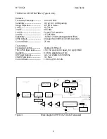
Страница 3: ...one 2nd LO 10 245 MHz Selectivity 6 dB at 20 KHz data passband filter AFSK Output Unsquelched 0dBm 3 0 KHz deviation Current Drain 25 mA Transmitter Frequency Control Crystal 18 MHz x 8 FSK AFSK Input level 150 mV p p 1200 baud 8 V p p 9600 Deviation 0 5 KHz adjustable at TNC RF Power Output 4 0 5 0 Watts into 50 Ohms VSWR Tolerance 3 1 Max Current Drain 1 0 Amp 13 8 Volts Figure 1 Block Diagram o...

Страница 4: ... FL2 455 KHz FL2 is a 20 KHz data bandwidth filter which supports 9600 baud operation Discriminator output is looped to U1 s auxiliary op amp which is configured as a DC coupled AFSK line driver Gain is set to provide 0 dBm AFSK output into a 600 Ohm load for approximately 3 0 KHz deviation A jumper configures the line driver feedback loop for HF noise reduction at 1200 baud AFSK reception Test po...

Страница 5: ...refully to confirm what type of carrier detection if any exists in your unit If you do have DCD activate it Important Note Some TNC s have software DCD circuits that may also require internal adjustments check your TNC manual and follow activation instructions carefully Other TNCs may not have a DCD at all or have a DCD indicator that is really nothing more than a mis labeled signal present indica...

Страница 6: ...starting with the MFJ 1270B Any other DCD equipped TNC such as the PK 96 and many others will also work with this data radio Use a 5 pin DIN to 5 pin DIN cable MFJ 5100 for connection to MFJ TNCs or the PK 96 Caution Not All TNCs have DCD Data Carrier Detect circuitry and your MFJ 8621 which has an unsquelched output will not work with those TNCs Pin Function 1 AFSK IN 150 mV pp 800 mV pp 2 GND 3 ...

Страница 7: ... left hand and center pins of each header For 9600 baud FSK operation remove JMP1 and set JMP 2 and JMP 3 in the varactor modulator positions center and right hand pins of the headers See Figure 3 on page 9 for placement of the jumpers on the pc board IMPORTANT NOTE JMP1 JMP2 and JMP3 are set for 1200 baud at the factory Always recalibrate the MFJ 8621 transmitter oscillator for frequency L6 after...

Страница 8: ... base To set TX deviation while monitoring RX AFSK first note the waveform height of average off air signals 2 2 V p p is typical for 3 KHz deviation Next key the MFJ 8621 transmitter via the CALIBRATE function on your TNC and adjust TNC output TX AFSK for a waveform of about the same height Confirming Deviation If a node in your area uses the X 1J2 version of theNET you can take advantage of that...

Страница 9: ... Box 06017 2341 Crystal Drive Fort Myers FL 33906 6017 Telephone 800 526 9825 FAX 813 936 3750 When ordering from JAN simply tell the sales person that you wish to order a pair of crystals for the MFJ 8621 Data Radio and give the operating frequency in MHz JAN has complete MFJ 8621 crystal specifications on file in their ordering system and no additional information is required Alternatively you m...

Страница 10: ...ce Locate and pull the existing receive crystal Y2 from its socket Carefully plug the new receive crystal in its place Figure 3 Crystal Locations and Calibration Adjustment Points For future reference label your pull out crystals for operating frequency and store them in a safe place Anytime you install new crystals you must readjust L4 and L6 for exact frequency calibration on the new channel see...

Страница 11: ...on the transmit crystal case in the 18 MHz range Next key the transmitter PTT line and adjust L6 for zero beat You must be precise any frequency error appearing at 18 MHz will be multiplied 8 times at 145 MHz Receiver Oscillator Your MFJ 8621 has a unique built in feature that allows you adjust the receiver oscillator by using the calibrated MFJ 8621 transmitter signal as a reference You ll need a...

Страница 12: ...nd why transmitters often use direct FM modulators which are especially adapted for FSK SENDING AND RECEIVING 9600 BAUD DATA Although 9600 baud packet is much faster than 1200 baud it is also much less forgiving of marginal signal paths For one thing you ll probably need about 5 6 dB in additional signal strength to overcome wideband noise generated by the receiver s unusually broad IF and audio p...

Страница 13: ...e Insufficient power source check voltage of power supply under load Wrong crystal installed at Y3 crystal should be in the 18 MHz range High VSWR antenna check antenna with bridge should be 2 1 or less Transmitter locked out because TNC is not equipped with DCD circuit IMPORTANT OPERATOR NOTES Your MFJ 8621 is specially designed to work with TNCs that are DCD equipped If your TNC does not have da...

Страница 14: ...as when the MFJ 8621 is subjected to a reversed polarity power If your Data Radio does not operate and you suspect that the line fuse is broken follow these steps 1 Remove the cover and inspect the fuse line It may be necessary to test the fuse for continuity 2 If the line is broken replace it with a length of 32 wire of approximately the same length You may optionally replace the line with a heav...

Страница 15: ...d to cover postage and handling 4 This warranty is NOT void for owners who attempt to repair defective units Technical consultation is available by calling 601 323 5869 5 This warranty does not apply to kits sold by or manufactured by MFJ Enterprises Inc 6 Wired and tested PC board products are covered by this warranty provided only the wired and tested PC board product is returned Wired and teste...

Отзывы: