background image

38   

Standard setting of the R-Net driving parame-

ters, profile 1, 2, 8, with 6 km/h

The parameter values in the following tables are 
selected so that the requirements of the valid legal 
regulations are fulfilled.

Profile allocation

Profile

Universal

1

Omni

2

Accompanying person

8

Standard setting of the R-Net driving parameters up to 6 km/h

Number of enable Drive Profiles

1

2

8

maximum / minimum

Forward Speed [%]

51/ 15

51/ 15

51/ 15

Reverse Speed [%]

30 / 10

30 / 10

30 / 10

Turn Speed [%]

without 

function

without 

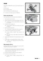
function

without 

function

Forward Acceleration

15 / 5

15 / 5

15 / 5

Forward Deceleration

30 / 10

30 / 10

30 / 10

Reverse Acceleration

10 / 5

10 / 5

10 / 5

Reverse Deceleration

15 / 5

15 / 5

15 / 5

Turn Acceleration

without 

function

without 

function

without 

function

Turn Deceleration

without 

function

without 

function

without 

function

Power [%]

100

100

100

Torque [%]

100

100

100

Содержание 2.322

Страница 1: ...W e m o v e p e o p l e Maintenance and Service manual Electric wheelchair Model 2 322 with operating module R Net en ...

Страница 2: ...e adjustment of the footplate 10 Angle adjustment of the footboard 11 Depth adjustment of the footboard 11 Leg support upper part 12 Adjusting the depth of the calf pads 12 Adjusting the height of the calf pads 12 Width adjustment of the leg supports 12 Stump support 13 Repositioning the leg stump support 13 Repositioning the leg stump cushion 13 Arm supports 14 Adjusting the height of the arm sup...

Страница 3: ... 21 Seat inclination camber 22 Replacing the adjustment motor for seat inclination 22 Wheels 23 Wheel change 23 Disassembly of the wheels 23 Assembly of the wheels 23 Changing the tyres 24 Disassembly of the tyres 24 Assembly of the tyres 24 Revetment 25 Replacing revetment parts 25 Fuses 26 Main fuse 26 Electronic security 26 Power module 26 Particularities of the 15km h version 26 Adjustment mod...

Страница 4: ... 2 8 with 10 km h 39 Standard setting of the R Net driving parameters profile 1 2 8 with 15 km h 40 Replace power steering lighting resp adjustment module 41 Power module 41 Steering Lighting module 41 Adjustment module 41 Plug assignment 42 Error indication 43 Error indication R Net 43 LCD Display 43 LED indicator 44 Error diagnostics 44 Functional checks 46 Checking the cable layout 46 Inspectio...

Страница 5: ... located on our website under www meyra com Requirements concerning workshop personnel Special knowledge is required to carry out the maintenance and service work described in this maintenance and service manual and may there fore only be carried out by educated qualified per sonnel We therefore offer vehicle specific courses that provide the specialised personnel with the re quired qualification ...

Страница 6: ... the safety and ex tends the life span of the wheelchair For highly strained wheelchairs for example in case of extreme strain user still growing users with changing disease patterns it is recommended to have the wheelchair checked maintained and if required adjusted semi annually Only original spare parts are to be used for all maintenance and service Before beginning with the service work check ...

Страница 7: ...he model description in the field Type resp Typ 2 The serial number beside the field SN TERM DEFINITIONS Here you will find explanations to the term used in this manual Service position The service position 2 describes a vehicle with corresponding seat position in order to enable e g unencumbered maintenance jobs In order to reach the electronic module you have to remove the battery cover 3 1 2 3 ...

Страница 8: ...8 OVERVIEW Model 2 322 R Net operating module ...

Страница 9: ...nd dirt parti cles Use only suitable tools View chapter Required tools and aids on page 9 Damages caused by the use of incorrect tools Replace loose screwed connections with thread safety with the respective nut or screw and new thread safety If new screws or nuts with thread safety not be available apply liquid thread safety compound with medium hardness e g Loctite 241 or Euro Lock A24 20 Damage...

Страница 10: ...r adjustment of the height loosen the respective clamp ing screw 1 Version 2 Loosen the respective clamping screw 2 to adjust the height Angle adjustment of the footplate 1 For this loosen the screw 3 so far that it no longer catches 2 Disconnect the toothing of the footplate and adjust the angle of the footplate 3 Retighten the screw 3 of the footplate In doing so the teeth of the angle adjustmen...

Страница 11: ...e side of the footboard slightly 2 Reposition the desired amount of distancer pieces on the lifted side 3 Pull press the distancers that are to be repositioned on the right side of the footboard outward from the retain ing rod 4 Note In certain angle settings of the footboard it is possible that a removal or placing of certain distancer pieces is not possible Then fold up the footboard 4 Repositio...

Страница 12: ...djusting the height of the calf pads Loosen the clamping screw 5 to adjust the height of the calf pad Width adjustment of the leg supports Width adjustment of the leg supports is achieved by reposi tioning the two leg support brackets Loosen the respective clamping screw 6 to adjust the width of the leg supports 5 4 6 4 ...

Страница 13: ...st unscrew the attachment screws 1 to reposition the leg stump support The reposition the bracket to the other side and attach it Repositioning the leg stump cushion First unscrew the screws 2 to reposition the leg stump cushion Then position the bracket turned by 180 on the other side aligned with the holes 3 and retighten with the screws 1 3 2 ...

Страница 14: ...ached when a mark becomes visible above the receptacle tube 2 Ensure the tight fit of the clamping screw 1 in order to prevent the arm support from sliding down Depth adjustment of the arm support pad The attachment screws 3 are to be removed for depth ad justment of the arm support pad e g after changing the seat depth Adjusting the clothes guard Loosen the clamping screws 4 to adjust the height ...

Страница 15: ... by moving the back sup port to a different position Therefore remove up to three attachment screws 1 on both sides Parallel repositioning of the back support Therefore observe the chapters Seat depth on page 19 and Depth adjustment of the arm support pad on page 14 1 1 1 ...

Страница 16: ...rt upholstery The back support upholstery 1 can be removed from the back shell by opening the velcro fastener Cable fitting The cable of the operating module is fastened back support bracket with a cable clamp 2 1 2 ...

Страница 17: ...ted in height after the clamping screw 2 has been slackened Attention The maximum height adjustment is indicated by the marking Afterwards retighten the clamping screw 2 Adjusting the position of the head support Loosen the clamping screws 3 to adjust the position of the head support Afterwards retighten the screws 3 Mounting the head support ErgoSeat The bracket 6 of the head support is mounted f...

Страница 18: ... arm sup ports outward inward To reposition the arm supports loosen the clamping screw 1 of the clamping guide Displace both arm supports by an equal distance after slackening the clamping screw 1 on both sides Attention The maximum seat width has been reached when a marking 2 is visible on the square tube 2 1 ...

Страница 19: ...ck support After removing the three attachment screws on both sides the back support can be positioned according to table Seat depth position of the back support Table Seat depth Position of the back support Seat depth cm 43 46 49 53 Pos back shell 5 4 3 2 Corresponds to the front assembly position of the adjustment plate a a 2 3 4 5 2 ...

Страница 20: ... the screws 3 to reposition the support brace 2 Position the support brace according to table front seat height 3 Reassemble the screwed connections 2 Then carry out a function test For this observe chapter Functional checks on page 46 Table Front seat height Seat inclination upper edge seat frame 2 4 6 8 10 Attachment position for screws A B C D E 1 1 1 2 2 A B C D E ...

Страница 21: ... the adjustment module 2 underneath the seat frame 2 Remove the upper and lower tube clip 3 of the adjust ment motor attachment In doing so watch for cables that might still be attached If required remove corresponding cable binders Assembly of the adjustment motor is done analogue in re verse order Then carry out a function test For this observe chapter Functional checks on page 46 1 3 2 ...

Страница 22: ...le 2 underneath the seat frame 2 Remove the screws 3 for attachment of the adjust ment motor for seat inclination adjustment In doing so watch for cables that might still be attached If required remove corresponding cable binders Assembly of the adjustment motor is done analogue in re verse order Then carry out a function test For this observe chapter Functional checks on page 46 2 1 3 3 ...

Страница 23: ...s Attention Never loosen the connection screws of the rim halves 1 to disassemble the wheel Danger of injury Disassembly of the wheels Take off the wheel by removing the respective wheel screw 2 Assembly of the wheels After replacing attaching the wheel secure the respective wheel screw 2 again with Loctite 243 and tighten For this observe chapter Torque according to DIN for screwed connections on...

Страница 24: ...r of injury 3 Unscrew the rim half connection screws 1 Assembly of the tyres Attention During assembly the rim halves may not damage the tube or let it be jammed 1 Place the tyre cover with crease free tube between the rim halves 2 Tighten the rim half connection screws 1 evenly For this observe chapter Torque according to DIN for screwed connections on page 49 3 Assemble the wheel For this observ...

Страница 25: ...s to be removed first Therefore loosen the retaining ring and pull off the lever Before replacing the rear or side revetment the cable connections for the lighting need to be opened and the cables made visible After assembly the respective levers need to the reattached with the retaining rings and the previously disconnected ca ble connections re established Then carry out a function test For this...

Страница 26: ...lso sees to a power limitation of the motors Particularities of the 15km h version Onthewheelchairversionwithamax finalspeedof15km h a bridge is located in the Inhibit socket 5 of the power module that limits the speed to 12km h Herefore also observe the document supplied with the power module Supplementary information 2 322 with R Net speed 15 km Adjustment module R Net All electric adjustments a...

Страница 27: ...n carry out a function test For this observe chapter Functional checks on page 46 Headlights The headlights 3 should be set in such a way that the light cone is visible on the road The lower edge of the light cone should be set at distance of 3 meters to the front of the electric wheelchair Note The headlights might need to be readjusted after me chanical adjustment of the seat angle Adjusting the...

Страница 28: ...ent first For this observe chapter Revetment on page 25 1 Turn the rear lamp housing counter clockwise 1 by about 15 and remove it 2 In doing so hold onto the dispersion disc to prevent it from also turning 2 Pull the defective bulb out of the dispersion disc Fitting 1 Insert the new bulb into the dispersion disc 2 2 Place the rear lamp housing onto the dispersion disc with an about 15 counter clo...

Страница 29: ...of the two lateral slots 5 and the wedge off the disper sion disc 6 carefully upward 7 2 Press the faulty spherical bulb slightly inwards turn and remove from the socket Fitting 1 Insert a new spherical bulb Push the side pins bay onet catch into the recesses of the bulb holder press lightly against the spring and then turn the bulb until the bayonet catch clicks into place 2 Mount the lens Theref...

Страница 30: ... push the sideward pin bayonet catch into the recess of the bulb holder press and turn lightly against the spring until the bayo net catch snaps into place 2 2 Mount the lens 4 Rear light Festoon bulb 6V C5W S8 5 Removal 1 Undo the securing screw 1 and remove the lens 2 2 Press the defective festoon bulb 5 against the holding pin and then pull it out of the holder Fitting 1 Insert the new festoon ...

Страница 31: ...nd remove it slanted toward the top 2 Lift all four pole clamps from the battery poles 3 3 Lift out the batteries with the handles resp straps 4 5 Mounting the batteries Assembly of the batteries is carried out analogue in reverse order to chapter Removing the batteries on page 31 Attention It is to be observed that the pole clamp cover is fas tened correctly above the battery poles Danger of fire...

Страница 32: ...harging Plugs that become hot during charging are to be replaced Technical requirements for the following drive batteries max charging voltage 28 5 V For sealed drive batteries up to 40 Ah 5 h 50 Ah 20 h Charging current 6 A For open sealed drive batteries from 40 Ah 5 h 50 Ah 20 h Charging current 8 A from 65 Ah 5 h 82 Ah 20 h Charging current 12 A Pin assignment of the charging plug B Pin 1 24 V...

Страница 33: ...apter Revetment on page 25 5 Pull the motor plug from the power module For this observe chapter Plug assignment on page 42 Open all necessary cable binders required for dis assembly 6 Remove the attachment screws 6 of the drive on both sides 7 Pull the drive out toward the front out of the rockers In doing so you might need to pull the rockers apart slightly Mounting the drive Assembly of the driv...

Страница 34: ...n fuse on page 26 2 Remove the front panel For this observe chapter Revetment on page 25 3 Remove the plus cable and the minus cable from the motor 4 Pull back the rubber buffer 1 from the motor 5 Remove the fixing screw 3 from the carbon brushes 2 6 Push the carbon brush retainer in the direction of the screw hole 4 7 Slightly pull the carbon brush retainer back form the motor opposite of the scr...

Страница 35: ...n brush is completely intact reassemble the carbon brush retainer and check the next one Assembly of the carbon brushes Assembly of the carbon brush is done analogue in re verse order to chapter Disassembly of the carbon brushes on page 34 When mounting the carbon brush after a visual check observe that the carbon brush receives the same posi tion as when being removed Collector The collector 11 l...

Страница 36: ... Adjusting the seat suspension For adjustment of the suspension the adjustment ring 2 is screwed forward or backward accordingly In doing so the following indications are valid Adjustment ring slightly screwed a soft suspension Also for people with little user weight Manufacturer setting Adjustment ring regularly pre tightened b medium suspension For regular sitting comfort Adjustment ring extreme...

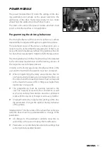
Страница 37: ...espective user at regular intervals In doing so the driving experience the physical limits of the user and the main field of operation must be considered When programming the delay value observe that on one hand extreme braking can endanger the driver on the other hand the braking distance must correspond to the maximum values of EN 12184 view chapter Brak ing distance on page 46 The programming m...

Страница 38: ...eters up to 6 km h Number of enable Drive Profiles 1 2 8 maximum minimum Forward Speed 51 15 51 15 51 15 Reverse Speed 30 10 30 10 30 10 Turn Speed without function without function without function Forward Acceleration 15 5 15 5 15 5 Forward Deceleration 30 10 30 10 30 10 Reverse Acceleration 10 5 10 5 10 5 Reverse Deceleration 15 5 15 5 15 5 Turn Acceleration without function without function wi...

Страница 39: ...eters up to 10 km h Number of enable Drive Profiles 1 2 8 maximum minimum Forward Speed 85 20 60 20 60 20 Reverse Speed 30 15 30 15 30 15 Turn Speed without function without function without function Forward Acceleration 15 5 15 5 15 5 Forward Deceleration 30 15 30 15 30 15 Reverse Acceleration 10 5 10 5 10 5 Reverse Deceleration 20 10 20 10 20 10 Turn Acceleration without function without functio...

Страница 40: ...eters up to 15 km h Number of enable Drive Profiles 1 2 8 maximum minimum Forward Speed 100 15 60 15 60 15 Reverse Speed 30 10 30 10 30 10 Turn Speed without function without function without function Forward Acceleration 15 5 15 5 15 5 Forward Deceleration 30 10 30 10 30 10 Reverse Acceleration 10 5 10 5 10 5 Reverse Deceleration 20 10 20 10 20 10 Turn Acceleration without function without functi...

Страница 41: ...fterwards to remove the attachment screws of the module 3 Remount the new module analogue in reverse order Attention It is to be observed that the cables are not damaged or bent when being placed Otherwise danger of fire through short circuits Previously removed cable ties are to be replaced Then carry out a function test For this observe chapter Functional checks on page 46 Power module The power...

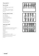
Страница 42: ...10 Steering potentiometer 11 R Net bus 12 Right lighting 13 Switch hand brake 14 Steering motor Adjustment module 15 R Net bus 16 free 17 Adjustment motor electric back support 18 Adjustment motor left leg support 19 free 20 free 21 R Net bus 22 free 23 Adjustment motor camber 24 Adjustment motor right leg support 25 Adjustment motor Recaro 26 free 1 2 3 4 5 6 7 8 9 10 11 12 13 14 15 16 17 18 19 2...

Страница 43: ...ble connection is defect 7205 Lamp short circuit left side 7209 Lamp short circuit right side 7206 Short circuit in cable left side 720A Short circuit in cable right side 7207 No connection signal left side 7208 No connection signal right side c Shows the location of the error Display Location of error JSM Operating module PM Power module ISM Lighting Adjustment module STLM Lighting Steering modul...

Страница 44: ...al connection to the left mo tor is open circuit Check the motor connection cable motor ca ble plug and motor The electrical connection to the left mo tor is defective short circuit Check the motor connection cable motor ca ble plug and motor The electrical connection to the right mo tor is open circuit Check the motor connection cable motor ca ble plug and motor The electrical connection to the r...

Страница 45: ...mo tor Check cables and connecting plugs This fault indication appears also if the lever of the drive motors is in the push mode position Move the lever to the drive mode position The battery voltage is too high downhill driving or the electrical connections are not O K Check the plug on the operating module and the battery connections The joystick communication is defective Check the connector ca...

Страница 46: ...end over the contour of the vehicle The cable may not be jammed or twisted Previously removed cable ties are to be re placed Inspection during standstill Check all screws attachments and connections in the area of the assembly or service work car ried out Do a visual check of the complete vehicle Switch to push mode and check the free move ment of the wheelchair Switch to drive mode switch the veh...

Страница 47: ...ed declares to have duly performed the measured declared in the maintenance checklist Reinstallment Designation SN No Serial no Year of construction Maintenance Inspection date Maintenance Inspection done by Signature Stamp of the executing workshop Before reimplementation the wheelchair is to un dergo a complete inspection The hygienic measures required for reinstall ment are to be carried out in...

Страница 48: ...the fastening of the steering and drive wheels Check the function of the quick release axles Wear of axle bushing The axles of the drive wheels do not show radial run out and run easily Wheel forks are not bent or torn Check the tyre condition and tyre pressure Check the condition functioning and smooth operation of the steering wheel suspension Screws with which the drive is attached to the vehic...

Страница 49: ... the annual maintenance jobs Tyres and rims Tread pattern depth of the tyres is greater than 1 5 mm Tyres free of damages or foreign bodies and not brittle Pressure front and rear Hubs do not show tears or raptures Hubs without axial run out of more than 2 mm Wheel attachment screws tightened with the value indicated in the table Inspection certificate filled out in the operating manual Torque acc...

Страница 50: ...Steering Lighting mod ule M2 Steering motor R1 Steering potentiometer S1 Switch hand brake S2 Switch drive push X7 Plugged connection steering potentiometer Lighting H1 Left rear light H2 Indicator rear left H3 Headlight left H4 Indicator front left H5 Headlight right H6 Indicator front right H7 Right rear light H8 Indicator rear right H9 Brake light H10 Amplified horn X1 Plugged connection lighti...

Страница 51: ...51 NOTES ...

Страница 52: ...D 32689 Kalletal Kalldorf Tel 49 5733 922 311 Fax 49 5733 922 9311 info meyra de www meyra de Your specialist dealer MEYRA 205 342 001 Status 2017 04 All technical modifications reserved Original Maintenance and Service manual ...

Отзывы: