background image


MR-GW User Manual | EN 

V 1.0 | Version 05/2020 

 Page 18 of 29 


METZ CONNECT GmbH | Im Tal 2 | 78176 Blumberg | Deutschland  
Tel. +49 7702 533-0 | Fax +49 7702 533-433 

more Documentation: www.metz-connect.com 

4.3.4


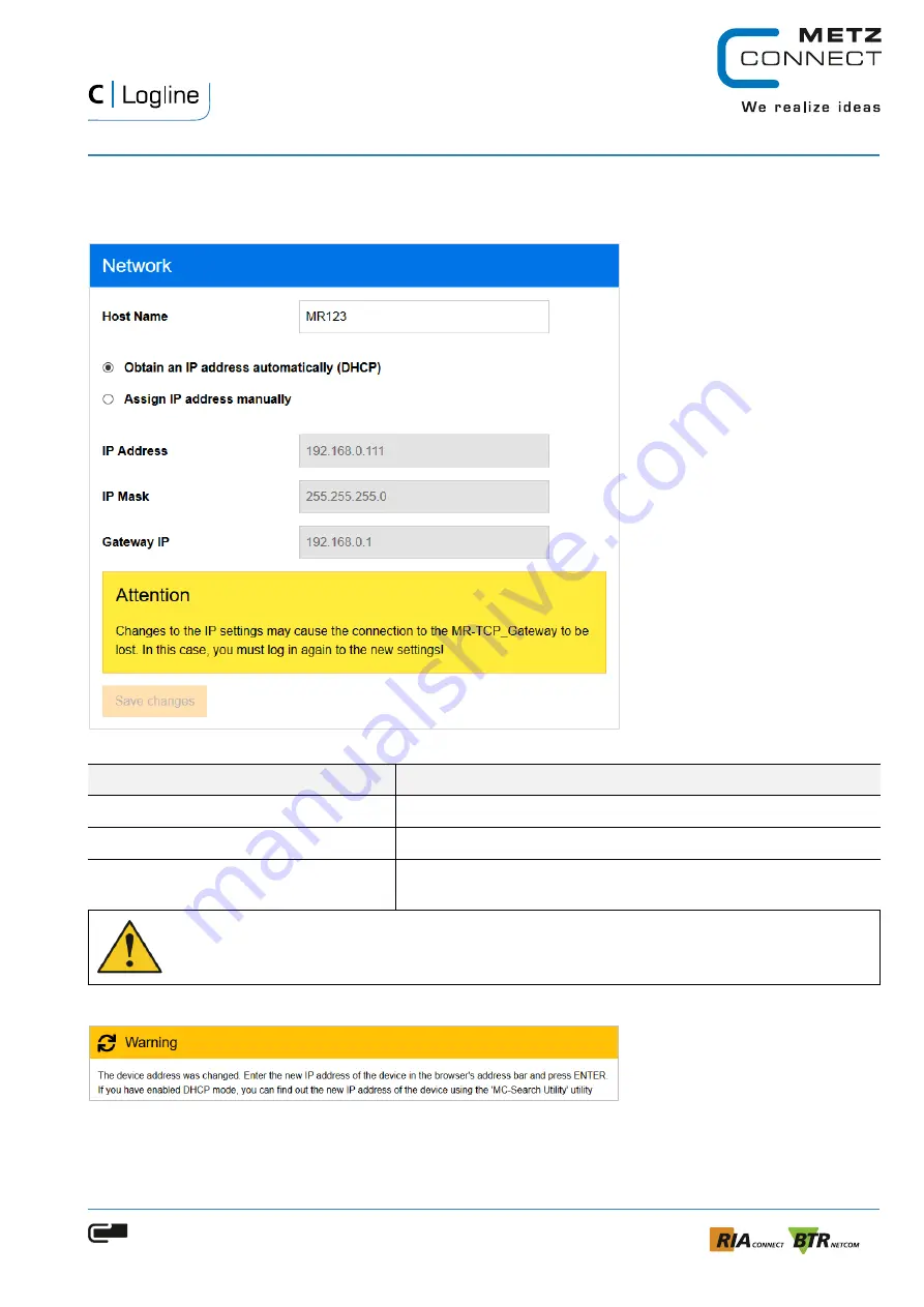
Network 

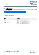
In the menu item 

Network

 the network settings are defined. 


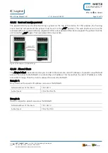
Figure 13 menu item Network 

Network settings 

Description 

Host Name 

Assign device name 

Obtain an IP address automatically (DHCP) 

IP address is automatically obtained via a DHCP server 

Assign IP address manually 

Device IP address, subnet mask, standard gateway are assigned 
manually 


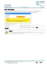
Attention 
After changing the network settings, connection to device may be lost. In this case, reconnect to the 
device using the new settings. 

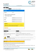
If the IP address is changed, the following message appears in the foreground of the browser: 


Figure 14 Warning when changing the IP address 

The web interface can be unlocked again by following the instruction and entering the new IP address in the 

address bar of the browser and confirming with ENTER. 


Содержание MR-GW

Страница 1: ... EN V 1 0 Version 05 2020 Page 1 of 29 METZ CONNECT GmbH Im Tal 2 78176 Blumberg Deutschland Tel 49 7702 533 0 Fax 49 7702 533 433 more Documentation www metz connect com MR GW Modbus TCP Modbus RTU Gateway User Manual ...

Страница 2: ...y 5 2 Description of the device 5 2 1 Technical Data 6 3 Installation 6 3 1 Installation location and state 6 3 2 Mounting 7 3 3 Dismounting und disposal 7 3 4 Connection 8 3 4 1 Connection diagram and principle diagram 8 3 4 2 Power Supply 9 3 5 Indicators 10 3 6 Communication interfaces 11 3 6 1 Ethernet interface 11 3 7 Ports 11 3 8 Timeout 11 3 9 RS 485 interface 11 4 Configuration 12 4 1 Web ...

Страница 3: ...z connect com 4 3 4 Network 18 4 3 5 RS 485 19 4 3 6 Security 20 4 3 6 1 User Password 20 4 3 6 2 Reset and reassign password 21 4 3 6 3 Allowed Clients 21 4 3 7 Monitoring 22 4 3 8 Discovery 23 4 3 9 Service 24 4 3 9 1 Settings 24 4 3 9 2 Firmware Update 25 4 4 MC Search Utility 26 4 4 1 Network settings 27 4 4 2 Configuration with MC Search Utility 28 4 5 Telnet access 29 ...

Страница 4: ... the system manufacturer or operator 1 2 Document history Version Date Author Description V 0 1 2020 04 29 MH Pre Version V 1 0 2020 05 26 MH MC Search Utility network settings 1 3 Safety instructions For the installation and use of the device the respectively valid industrial safety accident prevention and VDE regulations must be observed Skilled workers or installers are advised that they must d...

Страница 5: ...possible consequential damage Furthermore the warranty claim expires 1 6 Disclaimer of warranty The contents of this document have been carefully compiled and checked for conformity with the product in terms of hardware and software However deviations cannot be completely ruled out For this reason the information contained in this manual does not imply any obligation or warranty of any kind As a r...

Страница 6: ...100 Mbit LED yellow 10 Mbit Green LED housing Dimension W x H x D Weight Protection category housing terminal blocks 35 x 69 3 x 60 mm 1 378 in 2 728 in x 2 362 in 64 g IP40 IP20 Temperature range Temperature Operating Temperature Storage 5 C 55 C 23 F 131 F 20 C 70 C 4 F 158 F 3 Installation 3 1 Installation location and state The electrical installation and device connection may only be carried ...

Страница 7: ...sible for operating testing inspection and maintenance Figure 1 Mounting of MR GW 3 3 Dismounting und disposal Before disassembling it must be ensured that the MR GW has been taken out of operation and that all supply lines are de energized Once all supply lines have been removed use a slotted screwdriver to move the bolt on the MR GW outwards and remove the device from the mounting rail Figure 2 ...

Страница 8: ...erious bodily injury or considerable damage to property can occur Before working on the system it must be disconnected from the power supply The electrical installation and device connection may only be carried out by qualified personnel in compliance with VDE regulations and local regulations The correct connection must be checked before commissioning Incorrect connection can destroy the MR GW 3 ...

Страница 9: ...GW is 24 Volt DC 10 SELV and is either provided via a jumper plug and the NG4 power supply unit from METZ CONNECT Figure 5 or directly via the power supply terminals on the device Figure 5 Power supply and RS485 bus connection via jumper plug Danger The voltage of the power supply NG4 is 230 V AC Serious physical injury or considerable damage to property may occur Before working on the system it m...

Страница 10: ...ate LED Off MR Gateway is not ready to operate Link 10 100 LAN connection Green LED On MR Gateway is connected to LAN speed 100 Mbit s LED Off MR Gateway is not connected to LAN Yellow LED On MR Gateway is connected to LAN speed 10 Mbit s LED Off MR Gateway is not connected to LAN Busy TX RS 485 transmit Green LED On MR Gateway is transmitting RS 485 Data LED Off MR Gateway is not transmitting RS ...

Страница 11: ...eously master devices MODBUS TCP 32 Number of clients connected simultaneously master devices MODBUS RTU Over TCP 1 3 7 Ports Description Port MODBUS TCP IP Server network port 502 MODBUS RTU over TCP Server network port 4001 Webserver network port 80 Telnet Server network port 23 Broadcast search Server port 1030 3 8 Timeout The TCP IP connection timeout to MODBUS RTU Over TCP is 60 seconds When ...

Страница 12: ...net connection is established via a standard patch cable and the RJ45 connector on the device Figure 7 Ethernet connection with RJ 45 connector The following functions can be configured via the web interface Description Parameter Password based web client authentication adjustable Network settings IP address Subnet mask Gateway address Enable disable DHCP Allowed Client Connections RS 485 settings...

Страница 13: ...connect com 4 1 1 Default settings Description Parameter Default password admin TCP Protocol mode MODBUS TCP Network settings IP address 192 168 0 111 Subnet mask 255 255 255 0 Standard gateway 192 168 0 1 DHCP Disabled Allowed clients Subnet IP for clients Subnet mask Off 0 0 0 0 0 0 0 0 RS 485 settings Data bits 8 Baud rate 19200 Parity Even Stop bits 1 Modbus timeout 10 ms ...

Страница 14: ...ask 255 255 255 0 Standard gateway 192 168 0 1 To access the web interface and configure the MR GW the following steps must be performed 1 On your PC set LAN interface IP address e g to 192 168 1 100 and subnet mask to 255 255 255 0 2 Connect the PC to the device using an ETHERNET patch cable 3 Connect 24V power supply to the device 4 Start your web browser and type 192 168 0 111 in the address ba...

Страница 15: ...e login process has been successfully completed you will be taken to the start page of the web interface The menu item Overview displays the current settings of the MR GW Double clicking on the METZ CONNECT logo takes you directly to the product page on the homepage www metz connect com modbus gateway Figure 10 Overview of the current device settings 1 Navigation menu 2 Menu item 3 Information and...

Страница 16: ...533 433 more Documentation www metz connect com 4 3 2 Dynamic page adaptation The size and resolution of the web interface adapt to the display device used The window size of the web interface can be reduced and adjusted as required The navigation menu is collapsed Figure 11 Reduced representation of the web interface 1 Open navigation menu ...

Страница 17: ... TCP protocol mode In the TCP protocol mode menu item the operating mode Modbus TCP or Modbus RTU over TCP of the Modbus TCP interface is set Figure 12 menu item TCP protocol mode Mode Description Modbus TCP Gateway acts as a protocol converter 32 Modbus TCP client connections simultaneously Modbus RTU Over TCP Gateway acts as a transparent gateway 1 Modbus TCP client connection simultaneously ...

Страница 18: ...IP address is automatically obtained via a DHCP server Assign IP address manually Device IP address subnet mask standard gateway are assigned manually Attention After changing the network settings connection to device may be lost In this case reconnect to the device using the new settings If the IP address is changed the following message appears in the foreground of the browser Figure 14 Warning ...

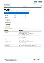
Страница 19: ...ed Figure 15 menu item RS 485 Parameter Description Baud Rate Setting the transmission speed min 1 200 bits s Bd max 115 200 bits s Bd default setting 19 200 bit s Bd Parity Setting the Parity Bit Odd Even None Default setting Even Stop Bits Number of Stop Bits One or Zwo Default setting One Stop Bit Modbus Timeout ms Timeout of the server client response time 1 5000 ms adjustable Default setting ...

Страница 20: ...set in the delivery status When logging in for the first time you are prompted to enter the default password Figure 17 Password request at first login Function Description OK Assign new password Later The next time you log in in a new browser window you will be prompted again to change the default password Ignore The next time you log in you will be prompted for the default password admin Note For...

Страница 21: ... assigned the jumper must be set to position OFF again The new password is now active Figure 18 Password jumper settings 4 3 6 3 Allowed Clients The Allowed client connections allow you to add or block remote client IP addresses to prevent unauthorized access The access to the MR GW is controlled by an IP address This means that if a client s IP address is in the accessible IP range then the clien...

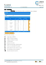
Страница 22: ... list of TCP clients and the current device status is displayed Figure 19 menu item monitoring 1 Supply voltage of MR GW 2 Modbus TCP Client connections 3 IP address of Modbus TCP Clients 4 Connection status 5 Duration of connection 6 Total and wrong Modbus TCP Client requests 7 Total and wrong Modbus RTU responses 8 Reset Modbus TCP Client connection counter 9 Drop of Modbus TCP Client connection...

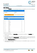
Страница 23: ...the start address in the From address input field and the end address in the To address field 2 Start discovery 3 The RS 485 interface will be searched and all METZ CONNECT Modbus RTU modules found during this process will be displayed in the Discovery results list Other manufacturers modules will also be shown if they support the MODBUS RTU standard identification function function 43 4 Activate ...

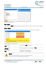
Страница 24: ...e update 4 3 9 1 Settings The current device settings are saved in a backup file on a PC and can be restored on any MR GW Figure 22 Backup and restore device settings Backup settings Start Save backup file cfg to local drive Restore settings Select file Select storage location and open backup file cfg Reset to defaults Start Reset MR GW to default settings Chapter 4 1 1 Default settings Attention ...

Страница 25: ...GW a firmware update can be carried out The latest firmware is available on the METZ CONNECT homepage at www metz connect com modbus gateway Figure 23 Make a Firmware Update Current Version Firmware Version of MR GW Firmware File Select file Select storage location and open firmware file mrg Attention Do not turn off power or disconnect network cable while flashing device firmware When the firmwar...

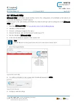
Страница 26: ...s must be configured via the MC Search Utility tool 1 Download MC Search Utility from www metz connect com modbus gateway 2 Installation of the Software 3 Connect 24V power supply to the device 4 Connect the device with an Ethernet patch cable to your PC 5 Run the installed of MC Search Utility 6 A list of all found devices appears in the selection list Note The MR GW which is being searched must ...

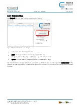
Страница 27: ...y Network settings The new IP address is displayed in the device list after a short time Double clicking on the device found in the selection list takes you directly to the web interface of the MR GW The MR GW is then configured via the web interface 1 Configuring network settings manually 2 DHCP Obtain an IP address automatically via a DHCP server The prerequisite for this is that a DHCP server i...

Страница 28: ...e configured via the MC Search Utility software tool if required Access to the web interface is not necessary The following functions can be configured using the respective tab pages tab Parameter Network Hostname IP address Subnet Mark Gateway address DHCP enabled disabled Allowed Client Connections RS 485 Baud rate Parity Stop Bits Timeout Terminator enabled disabled Mode Device mode MODBUS TCP ...

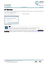
Страница 29: ...telnet to the device enter following command telnet xxx xxx xxx xxx IP address of MR GW Figure 27 Telnet Access Note If the Telnet client is not installed as the default application it must be enabled in the Windows settings Any other application that supports the Telnet protocol can also be used A detailed documentation of the Telnet commands is described in a separate software manual MR GW Telne...

Отзывы: