16
7 SG9H 70 en
4.5.4 Valve type,
VTYP
To compensate for nonlinearity of the position feedback
caused by the actuator linkage mechanism of a linear con-
trol valve, the appropriate selection must be made on the
VTYP
display.
After selecting
VTYP
on the display, press the
?
key
to enter the edit state and the
VTYP
starts to blink.
Select between two values
rot
or
LIn
using the
+
and
-
keys. The value
rot
indicates a rotary valve
and
LIn
a linear valve.
To conclude press the
?
key when the desired
value is shown on the display.
4.5.5 Actuator type,
ATYP
In order to optimise the control performance the device
needs to be informed about the actuator type.
After selecting
ATYP
on the display, press the
?
key
to enter the edit state and
ATYP
starts to blink.
Select between two values
2
-
A
or
1
-
A
using the
+
and
-
keys. The value
2
-
A
indicates a double acting
actuator and
1
-
A
a single acting actuator.
To conclude press the
?
key when the desired
value is shown on the display.
4.5.6 Maximum valve speed,
MAXS
Maximum Valve Speed parameter does not adjust the speed
of the valve. Parameter describes the pneumatic capacity of
SwitchGuard when compared to actuator size.
Once
MAXS
is displayed, press the
?
key to enter the
edit state and the
MAXS
will start blinking.
You may select between three values by pressing the
+
or
-
key. For small actuators select
FST
, medium
size actuators
STD
and large size actuators
SLO
. See
Table 3 for correct settings.
After the desired value is displayed, press the
?
key
to conclude the operation.
4.5.7 Positioner fail action,
PFA
This section describes the function of the actuator.
Set value according to Fig. 5 for double acting actuators. For
single acting actuators set value in the spring direction. This
action will also take place when the controller software dis-
covers a fatal device failure. See Fig. 5 for correct settings.
Once
PFA
is displayed, press the
?
key to enter the
edit state and the
PFA
will start blinking.
You may select between two values by pressing the
+
or
-
key. The
CLO
value indicates that the valve
ought to be closed in fail action situations. The
OPE
value indicates the valve to be opened in fail action
situations.
After the desired value is displayed, press the key
?
to conclude the operation.
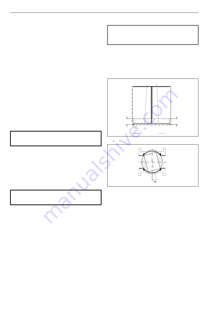
4.5.8 Valve dead angle,
A0
The
α
0
setting is made for segment and ball valves. This setting
takes into account the "dead angle"
α
0
of the valves. The entire
signal range is then used for effective valve opening 90° -
α
0
.
Use 0 % as the "dead angle" for the valves, which dead angle is
not known.
After selecting
A0
on the display, press the
?
key to
enter the edit state and
A0
starts to blink. The value
currently selected appears as a percentage (
%
) on the
display.
Modify the parameter value by pressing
+
or
-
keys alternately until the desired value appears on
the display.
Press the
?
key to make your selection and return
to the setting state.
4.5.9 Language selection,
LANG
Select between three languages
EnG
,
GEr
or
FrE
(English, German or French) using the
+
and
-
keys.
To conclude press the
?
key when the desired
value is shown on the display.
CAUTION:
Stroke times are defined by parameters
STOP
and
STCL
. Don’t try to adjust the speed with
MAXS
.
CAUTION:
Always adjust the maximum valve speed parameter accord-
ing to Table 3. Erroneous value may cause instability.
NOTE:
In case of signal direction (DIR) is same than positioner fail
action (PFA) 5 mA input signal is recommended as mini-
mum.
Fig. 15
Principle of setting
Fig. 16
Dead angle
100
80
60
40
20
0
0
20
40
60
80
100
α
0
α
0
POSITION
INPUT SIGNAL
= Basic setting
=
α
0 setting
Increasing input signal opens valve
Increasing input signal closes valve
cut-off safety range 2 ± 0.5 %
Содержание Switchguard SG9000H
Страница 36: ...36 7 SG9H 70 en SG9000H JB G 3 mA PT 5 6 4 G SG9_H_J ...
Страница 47: ...7 SG9H 70 en 47 ...


