Metso 5000B Скачать руководство пользователя страница 6

(3) and one seat (5) may fall out. If not, use a piece of 

wood or some other soft material to gently tap the ball 

from the non-insert end of the valve.

6.  Carefully remove the bottom seat (5) out of the body, 

BEING CAREFUL NOT TO SCRATCH THE BODY 

SEALING SURFACE BEHIND THE SEAT.

NOTE:  On ½” (DN15) valves, the stem cannot be removed 

with the stem seals and body seat in place.

7.  Press the stem (4) and lower stem seal into the valve 

body cavity and remove the upper stem seal. Then 

remove the stem and lower stem seal together from 

the valve body. It may be necessary to tap the stem 

with a piece of wood or some other soft material.

8.  Remove the all stem seals (8) and/or (7 & 24), BEING 

CAREFUL NOT TO SCRATCH ANY SEALING SURFACE 

INSIDE THE STEM BORE.

4.5 

Checking Parts

1.  Clean all disassembled parts.

2.  Check the stem (4) and ball (3) for damage. Pay 

particular attention to the sealing areas.

3.  Check all sealing and gasket surfaces of the body (1) 

and insert (2).

4.  Replace any damaged parts.

5.  Replace any fastener where the threads are damaged 

or have been heated, stretched or corroded.

6.  Replace any parts that have cracks, gouges or pits that 

will affect sealing.

NOTE: When ordering spare parts, always include the 

following information:

a.  Valve catalog code from Identification plate,

b.   

If the valve is serialized – the serial number 

(stamped on the valve body),

c.   From  Figure 10, the ballooned part number, part 

name and quantity required.

4.6 

Assembly

It is advisable to replace seats and seals if complete 

disassembly and reassembly become necessary.  Refer to 

the Repair Kit chart (see Table 3 or 4). A good lubricant,  

compatible with the flow media, MUST be applied to the 

threads on insert (2) to prevent galling during assembly.  

Lubricant should also be applied to the seats, seals, ball and 

stem to facilitate assembly and ease on initial operation of 

the valve.
Clean all valve components if not done previously.

Re-inspect all components for damage before reassembling 

the valve. Look for damage to the seating areas, stem, body 

and insert; and look for wear in the bearing areas. Replace 

any damaged parts.

Carefully clean and polish the ball (3) sealing surface: It 

should be free of all scratches and grooves.

If the ball is slightly damaged, it may be possible to smooth 

the sealing surface with crocus cloth or equivalent. If deep 

scratches are present, replace the ball.

1.  ½” (DN15) Series 5000 Valves

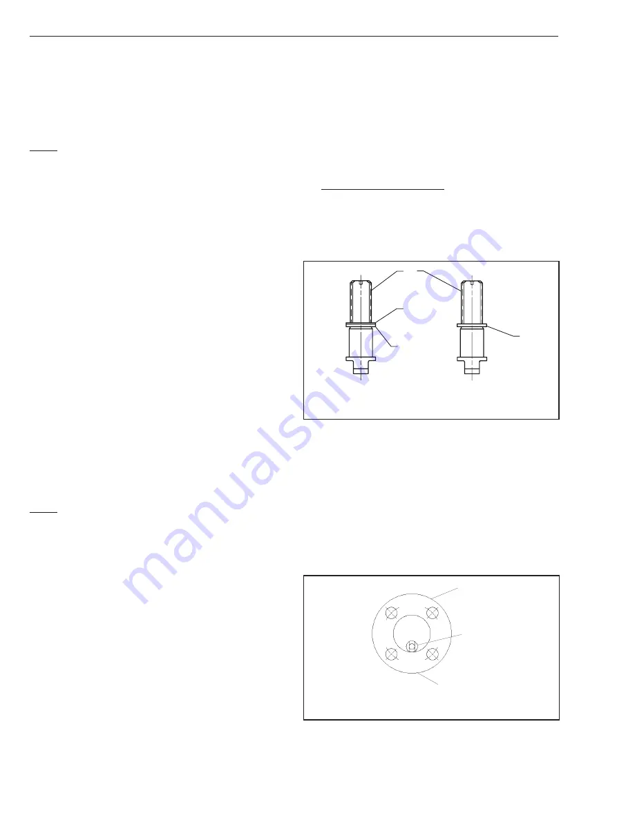
A.   Slide the lower stem seal (24) and secondary 

stem seal (7) (for fire-tested valves), or lower 

stem seal (8) (for non-fire-tested valves), over the 

threaded portion of the stem (4). The stem and seal 

subassembly must look like Figure 5.

B.   Place the body (1) on a flat surface resting it on 

both flanges with bonnet facing down.

C.   

Slide the stem and stem seal subassembly, 

threaded-end first, along the inside of the body 

bore towards the stem hole. The blade at the ball 

end of the stem must be vertical as seen from the 

insert end of the valve (see Figure 6). When the 

threaded end of the stem reaches the stem bore, 

guide it down into the bore and swing the entire 

subassembly up into the vertical position, allowing 

it to fall into place.

D.   Roll the entire valve on its flanges until the bonnet 

faces up. Then rotate the stem ¼ turn. The stem 

subassembly should look like (Figure 7) as seen 

from the insert end of the valve.

4

7

8

24

Fire-Tested

Non-Fire-Tested

Figure 5    Stem and Seal Subassembly

Body

Stem

Bonnet of Valve

Figure 6    Ball end of stem


IMO 4/18

IMO-50 EN

Содержание 5000B

Страница 1: ...IMO 50 EN 4 2018 Flanged Ball Valves Series 5000 Model B C 2 DN15 50 Class 150 300 Series 6000 Model B C 1 DN15 40 Class 150 300 Installation Maintenance and Operating Instructions ...

Страница 2: ... 5 Checking Parts 6 4 6 Assembly 6 4 7 Testing the Valve 8 5 HANDLE MOUNTING 8 6 ACTUATOR MOUNTING 8 6 1 Open Close Position Adjustment 8 7 SERVICE SPARE PART 8 8 HOW TO ORDER 11 IMO 4 18 2 IMO 50 EN READ THESE INSTRUCTIONS FIRST These instructions provide information about safe handling and operation of the valve If you require additional assistance please contact the manufacturer or manufacturer...

Страница 3: ... 9 Assembly date 1 3 Safety Precautions WARNING DO NOT EXCEED THE VALVE PERFORMANCE LIMITATIONS EXCEEDING THE PRESSURE OR TEMPERATURE LIMITATIONS MARKED ON THE VALVE IDENTIFICATION PLATE MAY CAUSE DAMAGE AND LEAD TO UNCONTROLLED PRESSURE RELEASE DAMAGE OR PERSONAL INJURY MAY RESULT WARNING SEAT AND BODY RATINGS THE PRACTICAL AND SAFE USE OF THIS PRODUCT IS DETERMINED BY BOTH THE SEAT AND BODY RATI...

Страница 4: ... Figure 3 Refer to the Section 4 MAINTENANCE for stem seal adjustment If there is weepage past the stem seals upon installation it means the valve may have been subject to wide temperature variations in shipment Leak tight performance will be restored by a simple stem seal adjustment described in the MAINTENACE section 3 3 Valve Insulation If necessary the valve may be insulated Insulation must no...

Страница 5: ... TIMES 4 2 Actuated Valve It is generally most convenient to detach the actuator and its auxiliary devices before removing the valve from the pipeline If the valve package is small or if it is difficult to access it may be more practical to remove the entire assembly NOTE To ensure proper reassembly observe the position of the actuator and positioner limit switch with respect to the valve before d...

Страница 6: ...he flow media MUST be applied to the threads on insert 2 to prevent galling during assembly Lubricant should also be applied to the seats seals ball and stem to facilitate assembly and ease on initial operation of the valve Clean all valve components if not done previously Re inspect all components for damage before reassembling the valve Look for damage to the seating areas stem body and insert a...

Страница 7: ... stem then rotating it so it sits flat on the seat face in the body 6 Insert the ball 3 rotating it on the stem 4 in the closed position If necessary turn the stem blade to align with the ball slot 7 Insert the second seat 5 so that the sealing surface of the seat is towards the ball see Figure 10 8 Insert the body seal 6 and gently press it into the groove in the body 9 After applying a lubricant...

Страница 8: ... PRECAUTIONS BE TAKEN BEFORE INSTALLING THE VALVE AND ACTUATOR BE SURE THE INDICATOR POINTER ON TOP OF THE ACTUATOR IS CORRECTLY INDICATING THE VALVE S POSITION FAILURE TO ASSEMBLE THESE TO INDICATE THE CORRECT VALVE POSITION COULD RESULT IN DAMAGE OR PERSONAL INJURY WHEN INSTALLING A LINKAGE KIT OR SERVICING THE VALVE ACTUATOR ASSEMBLY THE BEST PRACTICE IS TO REMOVE THE ENTIRE ASSEMBLY FROM SERVI...

Страница 9: ... 2 DN 15 3 4 DN 20 1 DN 25 1 1 2 DN 40 PTFE RKN 41TT RKN 43TT RKN 44TT RKN 46TT Filled PTFE RKN 41MT RKN 43MT RKN 44MT RKN 46MT PFA RKN 41BT RKN 43BT RKN 44BT RKN 46BT PEEK RKN 41LG RKN 43LG RKN 44LG RKN 46LG PFA Seat Seals RKN 41BP RKN 43BP RKN 44BP RKN 46BP Xtreme RKN 41XT RKN 43XT RKN 44XT RKN 46XT Table 5 Actuator Installation Maintenance and Operating Instructions Actuator IMO QPX 215 VPVL 55...

Страница 10: ...er Stem Seal 1 25 Stop Screw 2 26 Stop Screw Spacer 1 Fire tested valves only Upper and lower stem seals identical in Non Fire Tested valves NOTE Roundhandlesareavailableinplace of lever handles for the following valves 1 2 2 DN 15 50 Type 5150 1 2 1 1 2 DN 15 40 Type 5300 530S 3 4 1 1 2 DN 20 40 Type 6150 and 3 4 1 DN 20 25 Type 6300 16 19 17 16 21 8 25 26 1 5 3 5 6 2 22 8 7 24 4 or or 21 EXPLODE...

Страница 11: ...ard no entry C Chlorine N NACE O Oxygen STG Grounded V High Vacuum VC High Vacuum Certified DT 125 RMS Flange Finish 4 End Connection Size Range 11 Raised Face Non Fire Tite Non Trunnion 1 2 1 1 2 Full Bore 1 2 2 Standard Bore 31 Raised Face Fire Tite Non Trunnion 1 2 1 1 2 Full Bore 1 2 2 Standard Bore 5 Body Material Size Range 14 Aluminum Bronze 1 2 Std Bore Class 150 22 Carbon Steel WCB All 28...

Страница 12: ...00 Iporanga 18087 101 Sorocaba São Paulo Brazil Tel 55 15 2102 9700 Fax 55 15 2102 9748 Asia Pacific 238B Thomson Road 17 01 Novena SquareTower B Singapore 307685 Tel 65 6511 1011 Fax 65 6250 0830 China 11 F China Youth Plaza No 19 North Rd of East 3rd Ring Rd Chaoyang District Beijing 100020 China Tel 86 10 6566 6600 Fax 86 10 6566 2583 Middle East Roundabout 8 Unit AB 07 P O Box 17175 Jebel Ali ...

Отзывы: