background image


22 | 120 

blue’Log X series


The blue’Log can be expanded with several MX modules of the same ty

pe or with 

different MX modules. Please see the data sheet for your basic device for details of 
the maximum number of expansion modules. 


Fig. 11

: blue’Log with various MX modules


ATTENTION 


Order of installed MX modules 
When connecting MX modules to the basic device, the prescribed order has 
to be observed in order to ensure correct functionality of the modules. 


The number of arrows and lines at the bottom of the front panels of 

blue’Log and MX modules indicates the order 

of connection. Higher 

rated modules must not be installed before a module with fewer lines 
(e.g. two arrows/lines). For example, a module with three arrows/lines 
must not be connected before a module with two arrows/lines. 


Fig. 12: Order of installed MX modules 


Содержание blue'Log X series

Страница 1: ...blue Log X series X 1000 X 3000 X 6000 Operating Manual Version 20150922...

Страница 2: ...ol GmbH Spicherer Str 48 D 86157 Augsburg Tel 49 0 821 3 46 66 0 Web www meteocontrol com Technical support Tel 49 0 821 3 46 66 88 Fax 49 0 821 3 46 66 11 E mail technik meteocontrol de Details regar...

Страница 3: ...4 2 blue Log front panel 12 4 3 blue Log rear panel 13 4 4 Status LEDs 13 5 Installation 14 5 1 Safety instructions for installation 14 5 2 Cables and wiring 15 5 2 1 Permitted cable types for the bl...

Страница 4: ...mware update via USB 31 7 7 Showing the licenses on the display 31 7 8 Logging on to device websites 32 7 9 Logger master data 35 7 10 Ethernet 36 7 11 MX modules 36 7 12 User management 37 7 13 Licen...

Страница 5: ...alues 59 12 3 1 Diagrams 59 12 3 2 Real time values 60 12 4 Showing string measuring system measured values 61 12 4 1 Diagrams 61 12 4 2 Real time values 61 12 5 Showing battery system values 62 12 5...

Страница 6: ...1 14 4 5 cos U procedure 93 14 4 6 Q DI procedure 95 14 4 7 Q AI procedure 97 14 4 8 Q fix procedure 98 14 4 9 Q U procedure 99 14 4 10 Q P tan fix procedure 101 14 4 11 Q cos DI procedure 102 14 4 12...

Страница 7: ...or serious physical injury WARNING Possible danger Failure to comply with the warning notice may lead to death or serious physical injury CAUTION Hazard with a risk of material damage Failure to comp...

Страница 8: ...dashes level 2 List 1 Point A Point B List 2 Instructions describe steps which are to be carried out in the given order 1 Instruction 1 2 Instruction 2 Result of the operation Button names are shown i...

Страница 9: ...tallation all the manuals for system modules and components must be taken into account DANGER Danger from improper handling of the device The personnel responsible for installation operation and maint...

Страница 10: ...s and tools Faulty or non executed maintenance and repairs With Power Control meteocontrol GmbH accepts no liability for events and occurrences outside of its control such as the correctness of contro...

Страница 11: ...en their specialist training knowledge experience and familiarity with the relevant standards and regulations a qualified electrician is in a position not only to carry out work on electrical systems...

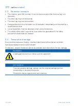
Страница 12: ...The safety of the blue Log and the user cannot be guaranteed if the safety precautions described are violated 3 4 Transport and storage Every product leaves our factory in perfect electrical and mech...

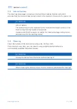
Страница 13: ...rvice since the blue Log housing needs to be opened meteocontrol GmbH accepts no liability for material damage owing to non compliance with this warning notice 3 6 Cleaning Clean the outside of the de...

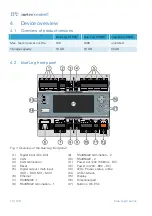
Страница 14: ...4 2 blue Log front panel Fig 1 Overview of the blue Log front panel 1 Digital input DI1 DI4 9 RS485 422 termination 2 2 CAN 10 RS485 422 2 3 CAN termination 11 Power out 24V 500mA DC 4 Reset 12 Power...

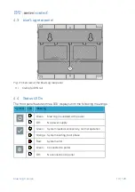
Страница 15: ...Status LEDs The front panel features three LED displays with the following meanings Symbol LED Meaning Green blue Log is supplied with power Off No power supply Green System loaded successfully norma...

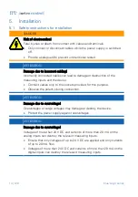
Страница 16: ...e device Connect cables only to the sockets provided for this purpose Observe the polarity during connection ATTENTION Damage due to overvoltage Overvoltages or surge voltages may damage or destroy th...

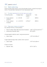
Страница 17: ...Type Finely stranded conductor U 24 V DC 1 mm2 H05V K Finely stranded conductor U 24 V DC 0 75 mm2 H05V K 5 2 2 Cable types for device connections Bus cabling inverters current sensors Recommended Da...

Страница 18: ...2YCYv TP manufactured by Lapp Kabel or an equivalent cable type This cable is suitable for laying in soil 2 For cables exceeding the given length the additional use of repeaters is necessary 3 Several...

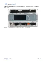
Страница 19: ...bols open closed lock above and below the DIN rail latch indicate whether or not the device is fixed 3 Check the secure connection of the blue Log to the DIN rail Fig 3 Secure mounting on a DIN rail T...

Страница 20: ...ion modules MX modules Fig 4 MX modules example RS485 422 ATTENTION Risk of damage when installing expansion modules Installing MX modules during operation of the blue Log can damage or destroy the bl...

Страница 21: ...Fig 5 Unlocking the fasteners Fig 6 Pulling off right hand side cap Keep the side cap at hand as you will need to reattach it to the right hand side of the expansion module later on to fasten the blu...

Страница 22: ...20 blue Log X series Fig 8 Plugging expansion module into the blue Log Now close the blue Log s fasteners again in order to fix the expansion module to the preceding device Fig 9 Attached expansion mo...

Страница 23: ...blue Log X series 21 120 Reattach the side cap to the right hand side of the expansion module and close the case locks Fig 10 blue Log and MX module connected and side cap attached...

Страница 24: ...When connecting MX modules to the basic device the prescribed order has to be observed in order to ensure correct functionality of the modules The number of arrows and lines at the bottom of the front...

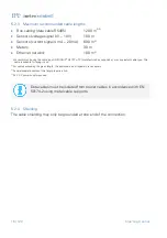
Страница 25: ...with limit values You should ensure that alternatively the following limit values are complied with IEC 61010 1 bzw EN CSA UL 61010 1 Power supply of Limited energy circuit with safety extra low volta...

Страница 26: ...as four multi inputs which can be used for either analog or digital signals Each port is configured individually via software 6 4 1 Analog input The analog inputs are freely configurable as Voltage in...

Страница 27: ...devices via the RS485 or RS422 bus Each RS485 RS422 interface adapts automatically and can be terminated individually via switches Please note the requirements for connecting bus devices in the enclo...

Страница 28: ...has finished booting The status LED on the device will light up ATTENTION Power supply During connection of the power supply it is imperative to ensure correct polarity 7 3 Establishing checking conn...

Страница 29: ...ied per bus Querying other sensors meters or string measuring systems in parallel is not possible Sensors and meters can be queried together if they communicate via modbus 7 3 3 Connections to analog...

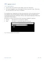
Страница 30: ...SC buttons take you to the blue Log display menus Fig 13 blue Log display Start menu 7 4 2 Setting language via quick access 1 To access the language settings press the ESC button on the display start...

Страница 31: ...egistered in the blue Log are shown in the user selection menu The individual users can be selected using the directional pad up and down and confirmed by pressing the OK button Once a user has been s...

Страница 32: ...s as well as the other parameters will now be retrieved automatically from the DHCP server Fig 16 blue Log display DHCP enabled 7 5 2 Setting the static network parameters Follow the instructions belo...

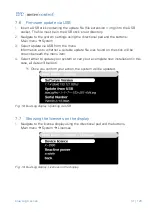
Страница 33: ...e menu Information as to whether a suitable update file was found on the stick will be shown beneath the menu item 4 Select either to update your system or carry out a complete new installation in thi...

Страница 34: ...e IP address in the address line of your web browser Alternatively you can address your blue Log with the following commands in the address line of your web browser Only one blue Log in the network ht...

Страница 35: ...rd information window 4 The wizard guides you step by step through the main set up points necessary for proper device operation The relevant set up step is shown in the navigation bar You can switch b...

Страница 36: ...34 120 blue Log X series After you close the wizard you will be taken to the blue Log s start page the so called Dashboard in the Cockpit menu Fig 23 Device websites Dashboard...

Страница 37: ...The connection power of your system agreed with the grid operator AC nominal voltage UNom Nominal voltage of your system Maximum apparent power SAV Maximum possible apparent power SAV of your system D...

Страница 38: ...omatic DNS address on off Primary DNS server Secondary DNS server 7 11 MX modules If you have expanded the blue Log data logger with one or more MX modules the MX modules connected will be displayed o...

Страница 39: ...ad only 4 Further personalized users can be set up in addition to the existing ones Users can be assigned to one of the aforementioned user groups service or user in order to specify authorizations fo...

Страница 40: ...nformation is displayed Date Automatically retrieved date and time 7 14 2 User defined time synchronization With user defined time synchronization a time server for synchronizing with system time can...

Страница 41: ...here In order to do this you will need the five digit system ID for the PV system on the portal the portal user name the portal password Alternatively the blue Log can be added on the portal itself v...

Страница 42: ...the online portal at regular intervals or at set times in order to transfer the measurement data collected 7 16 1 Reporting at regular intervals Specify whether the blue Log data logger should report...

Страница 43: ...make the following server settings FTP server name example ftp meteocontrol de FTP port default 21 Upload directory The directory must exist on the server it will not be created by the blue Log data...

Страница 44: ...e 3 Select the latest update highlighted in green in order to ensure your blue Log remaining up to date Clicking on the Start update button will update the system without deleting your data In the eve...

Страница 45: ...ils of configuration By acquiring the FTP Push Intraday X series license the frequency of data transmission can be increased The following interval setting selections are available 60 minutes 15 minut...

Страница 46: ...which clearly identifies the sensor 6 Via the drop down menu select one of the four ports MI 1 to 4 to which the sensor is connected If you have expanded your blue Log basic device using a multi I O...

Страница 47: ...menu select a sensor model connected to the input of the blue Log data logger e g ST RS485 TC T After selection the entry menu expands with further settings 4 Choose a device name which clearly ident...

Страница 48: ...elevant RS485 422 interface Configure the interface Fig 28 Device websites RS485 422 sensor interface configuration 7 Give the bus address of the sensor in the address box 8 By selecting Save the sens...

Страница 49: ...the meter to be connected is not included in the list you can select a generic template and configure the meter manually Please check in the data sheet whether the meter is compatible 5 Choose a devic...

Страница 50: ...ion Sourcing Recording of energy sourced from the electricity network Grid feed in Recording of energy fed into the electricity grid PV yield Recording of energy generated by the PV system Consumption...

Страница 51: ...u select a modbus energy meter After selection the configuration menu expands with further settings 4 Choose a device name which clearly identifies the meter 5 Select the operating mode of the meter m...

Страница 52: ...cted 9 Via the drop down menu select a role for the meter for correct assignment of meter values by the blue Log The following roles are available to choose from Sourcing Recording of energy drawn fro...

Страница 53: ...ogger to which the inverter is connected e g RS485 422 1 5 By selecting Start scan the previously selected bus interface will be scanned for connected inverters Fig 36 Device websites Inverter overvie...

Страница 54: ...with further settings 4 Choose a device name which clearly identifies the device 5 Via the drop down menu select an RS485 port 1 2 and or possibly MX module to which you have connected the device 6 Cl...

Страница 55: ...Via the drop down menu select a model After selection the configuration menu expands with further settings 4 Choose a device name which clearly identifies the device 5 Via the drop down menu select a...

Страница 56: ...41 Device websites Latest alarms In this window all alarms registered by the blue Log are listed Time device name type error code additional information and severity for each registered alarm are stat...

Страница 57: ...the button you can create a new contact address in the blue Log 4 Enter a contact name and an e mail address and confirm the details by clicking on the disk symbol in the very top right column 5 The...

Страница 58: ...s Alarm configuration 3 Enable monitoring 4 By selecting in the Contact s for e mail notification field a previously created contact see Section 11 2 Contact addresses can be selected Alarm messages r...

Страница 59: ...d a number of measured values can be shown in parallel If several sensors are selected only one measured value can be shown in each case 5 As an option the display of real time values can be selected...

Страница 60: ...an be shown in parallel If several meters are selected only one measured value can be shown in each case 5 As an option the display of real time values can be selected in addition to historical data i...

Страница 61: ...s All measured values available for the selected inverters will be shown If an individual inverter is selected a number of measured values can be shown in parallel If several inverters are selected on...

Страница 62: ...will appear in the same window Fig 47 Device websites Visualizing the measured data 12 3 2 Real time values 1 Navigate to the Cockpit area via the top navigation bar 2 Navigate to the Real time values...

Страница 63: ...measured values can be shown in parallel If several devices are selected only one measured value can be shown in each case 5 As an option the display of real time values can be selected in addition to...

Страница 64: ...ured values can be shown in parallel If several devices are selected only one measured value can be shown in each case 5 As an option the display of real time values can be selected in addition to his...

Страница 65: ...cted categories will be shown 5 As an option the display of real time values can be selected in addition to historical data in the diagram The resolution of the real time values is considerably higher...

Страница 66: ...ion menu Fig 52 Device websites Logbook 3 System events max 500 entries are listed in the logbook 4 Entries can be sorted according to Time Error code Error type and Description by clicking on the col...

Страница 67: ...ations according to the system size 14 1 1 Functions Receiving specifications regarding active and reactive power regulation from the grid operator Determining control values from the specifications i...

Страница 68: ...rid operator via the remote control system Depending on the remote control system used these are transferred to the blue Log via digital or analog signals Fig 53 Remote control system connection Digit...

Страница 69: ...e P DI P AI P fix Please see Section 14 3 Active power procedure for a detailed description of the active power procedures In addition to the type of specified target value the blue Log also provides...

Страница 70: ...e the blue Log also provides the option of specifying the rate at which the Q control values change gradient limitation in accordance with the grid operator s requirements see Section 14 4 17 Gradient...

Страница 71: ...s 69 120 14 1 4 Navigating to the Power Control website 1 Navigate to the PV system area via the top navigation bar 2 Navigate to the Power Control area via the left hand navigation menu Fig 55 Power...

Страница 72: ...ontrol system is connected to this blue Log Fig 56 Power Control Master data logger mode Input box Meaning Transfers to all slaves Specified control values are sent as general broadcast messages All b...

Страница 73: ...system is not connected to this blue Log Fig 57 Power Control Slave data logger mode Input box Meaning Receives general broadcast messages Specified control values are received from the blue Logs con...

Страница 74: ...constant cos or Q fallback value is specified as the control value Primary error procedure Selects the reactive power error procedure which is used if communication fails cos fix Configurable constan...

Страница 75: ...mperative for the parameters in this section to be correct in order to ensure the Power Control procedures functioning properly Input box Meaning Agreed connection power PAV Maximum feed in active pow...

Страница 76: ...Cog button Brings up the configuration settings for the selected active power procedure Enable Intelligent Power Limit IPL Enables the IPL function see Section 14 3 4 Intelligent Power Limit IPL Grad...

Страница 77: ...Meaning Limitation to agreed connection power PAV If enabled the active power is limited at the grid connection point to the agreed upon connection power PAV Fallback value Set fallback value as targ...

Страница 78: ...ned to the percentage target control values Step 1 In Step 1 the digital inputs used are configured Digital inputs of the blue Log are assigned to the active power procedure in the process Fig 60 P DI...

Страница 79: ...l come into force Fig 61 P DI Power Control procedure Reduction levels bitmask Input box Meaning Bitmask Number of the bitmask specified target value P The percentage control value for active power re...

Страница 80: ...for the analog signal are required These lie at the end and the start of the line Fig 62 P AI Power Control procedure Setting measured values Input box Meaning Analog input Description of the analog...

Страница 81: ...ed target value for example 60 or 70 percent is set as the permanent active power limit The PV yield active power can be limited with this procedure Fig 63 P fix Power Control procedure Setting the pe...

Страница 82: ...fied percentage active power will automatically be increased by the share of your on site energy consumption The IPL function can only be guaranteed if the system s power flows are recorded A variety...

Страница 83: ...20 Fig 64 Power Control Example IPL set up 1 PV generator 6 Power quality analyzer feed in meter 2 blue Log 7 Consumption meter 3 Inverter 8 Public electricity grid 4 RS485 bus 9 Grid connection point...

Страница 84: ...he inverter in a time discrete manner owing to the system s dead times The following figure is an exemplary illustration of time discrete control values Fig 65 Gradient limitation active power procedu...

Страница 85: ...blue Log X series 83 120 The configurable gradient is determined using the following formula Active power share for determining the gradient in PAV Time parameter for gradient limitation in s...

Страница 86: ...en using a feed in meter we recommend the use of an accumulating meter This takes into account the energy flow in all three phases and subtracts the consumption from the feed in while a non accumulati...

Страница 87: ...ol or reactive power regulation can be determined using various procedures In addition to the procedures further options allow for more settings to be specified e g the reactive power system control l...

Страница 88: ...he event of an error during standard procedure cos fix Set cos fallback value as control value in the event of an error with the selected cos procedure Q fix Set Q fallback value as control value in t...

Страница 89: ...re assigned to the specified control values via a bitmask Step 1 In Step 1 the digital inputs used are configured Digital inputs of the blue Log are assigned to the reactive power procedure in the pro...

Страница 90: ...ation of active signals is enabled at the digital inputs the control value assigned in each case will take effect Fig 69 cos DI Power Control procedure Specifications bitmask Input box Meaning cos Dis...

Страница 91: ...for the analog signal are required These lie at the end and the start of the line The excitation type for each point must also be given Fig 70 cos AI Power Control procedure Setting measured values In...

Страница 92: ...s control value The target value is specified as a constant displacement factor value To this end a configurable constant value is saved Fig 71 cos fix Power Control procedure Setting the constant spe...

Страница 93: ...ection point and transfers the measurements to the data logger for this purpose The logger then assigns the cos control value to the relevant power for example by using a two point characteristic curv...

Страница 94: ...h 4 interpolation points without hysteresis 4 point with hysteresis Curve with 4 interpolation points with hysteresis Interpolation point P1 to P4 Interpolation points 1 to 4 for the curve x P PAV P P...

Страница 95: ...he selected measuring device and transferring the results to the data logger The logger then assigns the cos control value to the relevant power using for example a two point characteristic curve Depe...

Страница 96: ...rce Selects the voltage source L1 L2 Outer conductor voltage phases L1 L2 L2 L3 Outer conductor voltage phases L2 L3 L3 L1 Outer conductor voltage phases L3 L1 Highest value Automatically selects the...

Страница 97: ...percentage specified control values via a bitmask Step 1 In Step 1 the digital inputs used are configured Digital inputs of the blue Log are assigned to the reactive power procedure in the process Fi...

Страница 98: ...mbination of active signals is enabled at the digital inputs the percentage control value assigned in each case will take effect Fig 77 Q DI Power Control procedure Specifications bitmask Input box Me...

Страница 99: ...for the analog signal are required These lie at the end and the start of the line The excitation type for each point must also be given Fig 78 Q AI Power Control procedure Setting measured values Inpu...

Страница 100: ...as control value The control value is specified as a constant percentage reactive power value To this end a configurable constant value is saved Fig 79 Q fix Power Control procedure Setting the consta...

Страница 101: ...easuring device and transferring the data to the data logger The logger then assigns the Q control value to the relevant voltage for example on basis of a two point characteristic curve Depending on t...

Страница 102: ...e Selects the voltage source L1 L2 Outer conductor voltage phases L1 L2 L2 L3 Outer conductor voltage phases L2 L3 L3 L1 Outer conductor voltage phases L3 L31 Highest value Automatically selects the h...

Страница 103: ...r assigns the control value Q to the relevant power via tan tan is stipulated here Fig 82 Q P tan fix Power Control procedure Specified reactive power curve Input box Meaning tan Constant value for ta...

Страница 104: ...rocedure requires a power quality analyzer that has been connected to the data logger and configured 14 4 12 Q cos AI procedure In this procedure the reactive power Q is used as control value The inpu...

Страница 105: ...wer quality analyzer that has been connected to the data logger and configured 14 4 14 Q cos P procedure In this procedure a cos value is derived from the target value and is converted into the reacti...

Страница 106: ...recording the voltage U at the grid connection point by the selected measuring device and transferring the measurements to the data logger This assigns the displacement factor to the relevant power fo...

Страница 107: ...all reactive power procedures cf Section 14 4 Reactive power procedure General fallback procedure The general fallback procedure allows an alternative reactive power procedure to be used in the event...

Страница 108: ...he permitted 4 20 mA range a target value will be specified via the selected general fallback procedure e g Q U If communication between the power quality analyzer PQA and the blue Log fails no valid...

Страница 109: ...hange in reactive power per second The gradient limitation relates exclusively to reactive power Q procedures e g Q DI and is always active when changing the specified reactive power With gradient lim...

Страница 110: ...using the following formula Target value specification range for reactive power regulation in SAV Max inductive reactive power capacity of the inverters in SAV Max capacitive reactive power capacity o...

Страница 111: ...the reactive power requirement of medium voltage cables and the transformer Fig 85 Power Control reactive power procedure Reactive power regulation Input box Meaning System control loop Enables react...

Страница 112: ...parameters have to be properly configured Agreed upon connection power PAV kW AC nominal voltage UNom kV Agreed upon maximum apparent power SAV kVA Parameter model transformer no transformer Transfor...

Страница 113: ...es to be taken into account using the chosen active power procedure 5 Are all necessary meters or a power quality analyzer installed in the PV system 6 Are all necessary meters or a power quality anal...

Страница 114: ...000 4 2 4 kV contact discharge 8 kV air discharge 20 C to 70 C 20 C to 85 C IP 20 2000 m 80 2 Wall installation electrical distribution board control cabinet 147 mm x 110 mm x 63 mm W x H x D includin...

Страница 115: ...mA Digital Voltage output 20 60 V DC corresponding to supply voltage max 45 W in total of all digital outputs basic module and MX modules max 200 mA per output The following options are available for...

Страница 116: ...ored Basic module and expansion modules 3 Max 12 Max 20 Max 28 Web Portal compatibility safer Sun Professional VCOM virtual control room Remote access via portal 4 Visualization via websites Live valu...

Страница 117: ...X 3000 16 GB X 6000 32 GB 16 Environmental protection and disposal Old and defective devices should be disposed of in accordance with national and local environmental and recycling regulations Electro...

Страница 118: ...22 MX module Multi I O MX module GPRS Wir erkl ren dass die genannten Produkte folgenden Dokumenten und Normen entsprechen We declare that the products described above are in compliance with following...

Страница 119: ...1 Cadmium 0 01 Hexavalent chromium 0 1 Polybrominated biphenyls PBB 0 1 Polybrominated diphenyl ethers PBDE 0 1 Since we are guaranteed RoHS compliance by our suppliers we meteocontrol GmbH can confir...

Страница 120: ...29 Fig 16 blue Log display DHCP enabled 30 Fig 17 blue Log display DHCP disabled 30 Fig 18 blue Log display Updating via USB 31 Fig 19 blue Log display Licenses on the display 31 Fig 20 Logging on to...

Страница 121: ...system 61 Fig 50 Device websites Selecting battery system diagram options 62 Fig 51 Device websites Selecting Power Control diagram options 63 Fig 52 Device websites Logbook 64 Fig 53 Remote control...

Страница 122: ...g 76 Q DI Power Control procedure Selecting the digital inputs 95 Fig 77 Q DI Power Control procedure Specifications bitmask 96 Fig 78 Q AI Power Control procedure Setting measured values 97 Fig 79 Q...

Страница 123: ......

Страница 124: ...66 88 Fax 49 0 821 3 46 66 11 technics meteocontrol de www meteocontrol de en Text and illustrations represent state of the art technology at time of printing Subject to technical modifications We ass...

Отзывы: