background image

21

MOTORES

Tipo general:

Industrial de servicio pesado/Comercial

Marca:

Kawasaki

Modelos:

FH

480V (16 HP), FH541V (17 HP) FH580V (19 HP)

Potencia:

16 HP, 17 HP y

 19 HP

Tip

o:

Motores de eje vertical, 4 ciclos, gasolina

Desplazamiento:

16

 HP

 = 472cc, 17 HP = 585cc, 19 HP = 585cc

Cilindros:

2 con camisas de hierro fundido

Controlador:

Controlador tipo mecánico con control de velocidad variable.

Aju

ste

s:

16 HP, 17 HP y 19 HP = 3600 RPM (+/-100 RPM), vacío fijado

en 1550 RPM (+/-150 RPM).

Grupo de 

escape:

Silenciador de tubo de escape simple de montaje lateral

Conjunto de 

bomba de 

combustible:

Bomba de combustible tipo pulso con filtro en línea

Conjunto de bomba de aceite:

Consulte las 

especificaciones del 

fabricante

Grupo de 

válvula:

Consulte las especificaciones del fabricante

Arrancador/Sistema eléctrico:

Encendido electr

ónico con arrancador de retroceso, encendido

de estado sólido

PLATAFORMA DEL MOTOR

Espesor:

Acero calibre 7

Tanque de combustible:

Polietileno sin costuras, 6 galones (19.0 litros) con sujetavasos

Ruedas motrices/Llantas:

SWZU36A - 16 x 6.50-8 sin cámara neumática, de cuatro capas

SWZU48V y 52V - 18 x 8.50-8 sin cámara neumática, de cuatro

capas

Frenos:

Fre

nado dinámico mediante sistema de transmisión hidráulica

Eje

s:

1" cónico

Barras del mango:

1-1/4" diámetro

SISTEMA DE TRANSMISIÓN

Tip

o:

Transmisión hidráulica con dos bombas de desplazamiento

variable y dos motores de hierro fundido y alto torque

Hidro bombas:

Dos bombas 

Hydro-Gear BDP 10A con válvulas de descarga

para el desplazamiento sin operación del motor

Motores de la rueda motriz:

Dos motores de alto torque modelo TG de 15 pulgadas cúbicas

Grupo de refrigeración de fluido hidráulico:

Depósito de refrigeración de nylon, con capacidad de 4 cuartos,

usa fluido SAE 20W50 y filtro de 10 micrones

Control de dirección/desplazamiento:

Mangos de 

control independiente para cada rueda, apriete

para moverlo desde adelante a neutral y a reversa, palanca de

bloqueo de neutral, rango de velocidad controlado con palanca

simple (de diseño patentado), ajuste de alineación en el campo

con herramienta suministrada.

Frenos de 

estacionamiento:

Tambor de 7.5", freno de banda, uno en cada rueda

Válvulas de 

descarga:

Permite el movimiento sin funcionamiento del motor

Eje

s:

Ejes cónicos de motor de 1"

Mazo de cables:

Alambre calibre 

14

Grupo de 

seguridad:

Sistema de presencia del operador de actuación manual

(diseño patentado) con embrague/cuchilla y bloqueo de

transmisión para apagar el motor

Rango de 

velocidad hacia 

adelante:

0 a 7.4 mph (11.8 Kph)

Rango de 

velocidad en 

reversa:

0 a 3.0 mph (4.8 Kph)

Fecha de publicación: Julio, 2006

Especificaciones sujetas a cambio sin previo aviso

ESPECIFICACIONES TÉCNICAS

Содержание SCAG POWER EQUIPMENT SWZU Series

Страница 1: ...H ASSISTANCE IN MAINTENANCE AND AD JUSTMENT PROCEDURES TO KEEP YOUR MOWER PERFORMING TO MAXIMUM EFFI CIENCY THE SPECIFIC MODELS THATTHIS BOOK COVERS ARE CONTAINED ON THE INSIDE COVER BEFORE OPERATINGY...

Страница 2: ...d storage of the equipment FAILURE TO FOLLOW SAFE OPERATING PRACTICES MAY RESULT IN SERIOUS INJURY WARNING Keep all shields in place especially the grass discharge chute Before performing any maintena...

Страница 3: ...iderations 6 7 Maintenance and Storage 7 8 Initial Run In Procedures 8 Mower Operation 8 9 Belt Tension 9 Cutter Deck Adjustments 10 11 Cutter Blades 11 Custom Cut Baffle Adjustment 11 12 Neutral Adju...

Страница 4: ...tes 23 Illustrated Parts List SWMU 36 Cutter Deck 24 25 SWMU 48 52 Cutter Decks 26 27 Cutter Deck Frame 36 28 29 Cutter Deck Frame 48 52 30 31 Engine Deck 32 33 Drive And Brake Components 34 35 Handle...

Страница 5: ...n and facing the forward travel direction For pictorial clarity some illustrations and figures in this manual may show shields guards or plates open or removed Under no circumstances should your mower...

Страница 6: ...2 CE Mark Transmission Choke On Start Spring Tension on Idler Oil Off Stop SYMBOL DESCRIPTION SYMBOL DESCRIPTION ISO Symbols Spinning Blade 48071S Parking Brake Falling Hazard Thrown Object...

Страница 7: ...ting Element Basic Symbol Cutting Element Disengage Continuously Variable Linear Read Operator s Manual Keep Bystanders Away Pinch Point 481039S SYMBOL DESCRIPTION SYMBOL DESCRIPTION Hourmeter Elapsed...

Страница 8: ...oaded by using the model and serial number or use the contact form to make your request Please indicate the complete model and serial number of your Scag product when requesting replacement manuals If...

Страница 9: ...brake and move the neutral latches to neutral 9 The discharge chute must always be installed and in the down position on the side discharge cutter deck except when the Scag optional grass catcher or m...

Страница 10: ...verse maintain a constant lookout to the rear of the machine and mow slowly WARNING DO NOT use your hand to dislodge the clogged discharge chute Use a stick or other device to remove clogged material...

Страница 11: ...ing or adjusting the machine Wait for all movement to stop before adjusting cleaning or repairing 3 Never make adjustments to the machine with the engine running unless specifically instructed to do s...

Страница 12: ...to operate this machine 2 Before starting the engine Check the oil level in the engine and the hydraulic reservoir NOTE Use gasoline with an octane rating no less than 87 and a maximum of 10 ethanol F...

Страница 13: ...ce turning and maneuvering with the hand controls before engaging the cutter blades 7 While squeezing the steering brake levers with both hands release both neutral latches NOTE Top speed is suggested...

Страница 14: ...remove the key 2 Support the cutter deck with four blocks you will be removing the hair pins to make this adjustment 3 Remove the front hair pins from the front deck supportpins 4 Loosen the jam nuts...

Страница 15: ...et in three 3 different positions for optimum performance A 3 Position baffle is installed using the top set of holes on the front baffle welded inside the cutter deck See Figure 6 Page 12 The Velocit...

Страница 16: ...he adjust ment nut See Figure 9 5 Turn the adjustment nut clockwise just until the wheel turns rearward Make a note of the position of the adjustment nut To adjust neutral split the difference between...

Страница 17: ...ost often be used 2 Squeeze the steering control levers and release the neutral latch Slowly release the steering control levers allowing the machine to move forward WARNING BEFORE ATTEMPTINGTO MAKE A...

Страница 18: ...is against the stop on the handle bar the brake levers on the brake shaft weldment are against the stops on the engine deck 2 Adjust the brake actuator rod on either side of the machine to obtain prop...

Страница 19: ...se X Drain hydraulic system and replace oil filter See page 16 X Grease caster wheel pivot shafts Chassis grease see instructions below X Replaceenginefuelfilter See engine operator s manual X Adjust...

Страница 20: ...ter in the hydraulic oil 2 Place a suitable container under the hydraulic oil drain Remove the fill cap from the reservoir Remove the drain cap from the T Fitting located on the hydraulic system filte...

Страница 21: ...place the engine oil filter Thereafter replace the oil filter every 100 hours of operation or every month whichever occurs first Refer to Engine Operator s Manual for instructions Engine Air Cleaner F...

Страница 22: ...ut Grass in Cutting Path Incorrect blade sharpening Sharpen blades Low engine RPM Run engine at full 3600 RPM Belt slipping Adjust belt tension Deck plugged grass accumulation Clean underside of deck...

Страница 23: ...change Wavy Appearance direction of cut High Low Scalloped Cut or Rough Contour Width of Deck SGB020 Width of Deck SGB021 Width of Deck SGB023 Uneven Cut on Flat Lift worn off of blade Replace blade...

Страница 24: ...st for conditions Wet grass Cut grass after it has dried out Step Cut Blades not mounted evenly Adjust pitch and level Ridge in Center of Cutting Path Bent blade Replace blade Internal spindle failure...

Страница 25: ...g through hydro drive system Axles 1 tapered HandleBars 1 1 4 diameter DRIVE SYSTEM Type Hydro drive with two variable displacement pumps and two cast iron high torque motors Hydro Pumps Two Hydro Gea...

Страница 26: ...Arm Heavy duty dual ball bearing mounting Cutter Deck Belts B section with Kevlar cord ADDITIONAL SPECIFICATIONS OPTIONAL ITEMS ATTACHMENTS Fabric Grass Catcher GC F4 Grass Catcher with 4 cubic ft ca...

Страница 27: ...23 NOTES...

Страница 28: ...CD36A 33 34 15 56 56 59 46 50 56 R 63 20 21 22 23 24 25 26 27 22 28 29 30 A 32 60 31 32 9 10 9 8 19 19A 65 67 33 47 40 39 4 61 52 49 49 51 52 53 54 57 58 48 33 49 62 33 48 38 35 33 10 8 9 9 11 36 70 6...

Страница 29: ...Elastic Stop 38 48038 Guide Roller 36A CUTTER DECKS Ref Part No Number Description Ref Part No Number Description 39 04001 09 Bolt Hex Head 5 16 18 x 1 40 451118 Roller Shaft 41 48926 Tapered Hub 42 4...

Страница 30: ...4 4 5 30 31 32 33 34 35 36 37 32 38 39 40 21 22 22 23 20 A 55 8 64 64A 18 63 65 B 61 62 63 20 22 23 21 22 C C 57 9 D D 20 23 21 22 22 59 68 44 11 57 12 9 67 18 10 9 8 To B 60 56 45 65 To A 50 46 14 46...

Страница 31: ...er Outside x x 37 43296 Spacer Inside x x 38 481025 Seal Cutter Spindle Bottom x x Ref Part No No Description 48 52 48V 52V CUTTER DECKS 39 43297 Spindle Bushing x x 40 481035 Nut Spindle x x 41 48162...

Страница 32: ...28 36A DECK FRAME 1 2 3 4 5 4 7 7 8 9 10 11 12 13 14 15 23 19 16 22 SWZU06DF36 24 25 6 25 6 17 18 20 21 17...

Страница 33: ...3 8 391 x 938 x 105 11 04019 04 Nut 3 8 16 Serrated Flange Hex Head 12 45325 Yoke Caster Wheel 13 04001 80 Capscrew Hex Head 1 2 13 x 6 1 2 14 04021 07 Locknut 1 2 13 Elastic Stop 15 9276 Flat Free Ti...

Страница 34: ...30 48V AND 52V DECK FRAME SWZU06DF48 52 1 2 3 4 5 4 6 6 7 8 9 10 11 12 13 14 25 21 18 15 24 22 23 24 22 20 19 16 17 16...

Страница 35: ...Flatwasher 3 8 391 x 938 x 105 10 04019 04 Nut 3 8 16 Serrated Flange Hex Head 11 45325 Yoke Caster Wheel 12 04001 80 Capscrew Hex Head 1 2 13 x 6 1 2 13 04021 07 Locknut 1 2 13 Elastic Stop 14 9276...

Страница 36: ...32 ENGINE DECK SWZU 06 ED 27 16 KAI 17 KAI 19 KAI ONLY 10 8 9 6 8 7 5 4 29 29A 22 24 25 14 13 18 19 28 23 11 12 20 21 26 19 1 19 16 24 2 20 3 Push Arms...

Страница 37: ...Brace x x x 13 04043 04 Flat Washer 391 x 938 x 105 x x x 14 04021 09 Nut 3 8 16 Elastic Stop x x x 15 04021 08 Nut 1 4 20 Elastic Stop x x x 16 461745 Engine Deck 16 Wide w decals x x x 17 04003 09...

Страница 38: ...NTS 50 47 50 24 25 34 36 37 41 1 39 38 38 51 42 42 46 47 53 44 35 SWZU06D BC 3 43 2 7 8 A 4 6 26 27 28 33 31 32 29 30 23 22 B 5 B 54 55 56 57 58 59 60 56 17 12 13 15 14 16 20 18 19 21 49 4 52 A 2 11 7...

Страница 39: ...20 x 2 3 4 x x x 29 422534 Plate Backing x x x 30 48030 09 Clamp x x x 31 04021 10 Nut 5 16 18 Elastic Stop x x x 32 481716 Rubber Pad Clutch Stop x x x 33 422533 Retainer Clutch Stop x x x 34 04001 1...

Страница 40: ...13 11 18 19 28 10 42 12 40 SWZU05HANSF 40 60 75 82 61 86 85 80 81 88 79 B 76 99 65 98 73 93 78 79 B 95 58 63 48 61 88 37 66 52 82 66 6 73 46 43 70 44 45 51 42 47 49 11 24 72 C 3 C 33 78 53 97 84 57 9...

Страница 41: ...5 16 18 Serrated Flange 46 422795 Plate Side 47 43536 Spacer Neutral Bearing 48 48409 Bearing Speed Ctrl Bellcrank 49 04001 69 Hex Head Bolt 5 16 18 x 1 3 4 50 48494 02 Spring Return 56 43415 Bushing...

Страница 42: ...0 18 12 B 5 6 7 29 22 25 10 10 19 19 21 27 26 28 10 10 G F 23 23 23 11 6 6 11 E D 22 23 13 12 15 32 C 1 2 3 5 9 4 14 2005SWZ HA 24 11 11 28 11 11 11 23 23 20 12 6 C 23 A A 31 29 4 23 12 8 J H 30 33 16...

Страница 43: ...482477 Tee 3 8 O Ring x JIC x 1 2 Hose 16 422794 Strap Hydraulic Tank 17 422793 Bracket Hydraulic Tank 18 04017 16 Capscrew 5 16 18 x 75 Serr Flange 19 48603 04 O Ring 20 482266 01 Elbow 9 16 O Ring x...

Страница 44: ...40 Overhaul Seal Kit 1 2 3 4 5 6 7 8 9 10 28 24 26 11 12 13 14 15 22 23 20 21 18 17 16 19 27 29 25 24 PORT A SIDE PORT B SIDE HYDRAULIC PUMP ASSEMBLY...

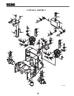
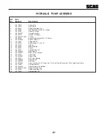
Страница 45: ...50315 Ball Bearing 17 x 40 x 12 13 HG 51161 Lip Seal 14 HG 50329 Retaining Ring 15 HG 50951 Spacer 16 HG 70331 Cylinder Block Kit 17 HG 2003014 Block Spring 18 HG 2003017 Block Thrust Washer 19 HG 514...

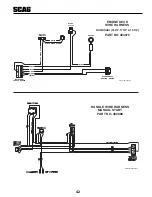
Страница 46: ...WZU06WH483075 WIRE HARNESS ADAPTER ENGINE BLADE CLUTCH GROUND BLACK KAWASAKI 16 HP 17 HP 19 HP ENGINE DECK WIRE HARNESS PART NO 483075 E A F B G C H D INSTRUMENT PANEL HARNESS BLACK BLUE WHITE WHITE Y...

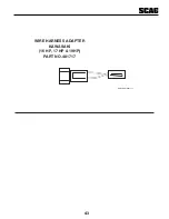
Страница 47: ...43 WIRE HARNESS ADAPTER PART NO 481717 KAWASAKI 16 HP 17 HP 19HP SWZU06WH481717...

Страница 48: ...OTATING BLADES AND BELTS DO NOT OPERATE UNLESS GRASS CATCHER MULCHING KIT OR DISCHARGE CHUTE IS INSTALLED 483406 48404 5 6 4 1 WARNING WARNING DO NOT OPERATE WITHOUT DISCHARGE CHUTE MULCHING KIT OR EN...

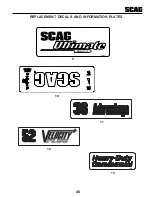
Страница 49: ...45 REPLACEMENT DECALS AND INFORMATION PLATES 11 482297 13 FAST SLOW PARKING BRAKE OFF ON 10 12 SWZU 481906 9...

Страница 50: ...alcraft Made in USA 6 483441 Decal Instrument Panel Rear 7 483404 Decal Sulky Attachment 8 483402 Decal Belt Cover 9 481906 Decal SWZU Ultimate 10 481438 Decal Instrument Panel Front 11 482297 Decal 3...

Страница 51: ...47 NOTES...

Страница 52: ...nd the expense of returning it to the owner after repair will be paid for by the owner Scag s responsibility is limited to making the required repairs and no claim of breach of warranty shall be cause...

Страница 53: ...a cargo del propietario La responsabilidad de Scag se limita a la realizaci n de las reparaciones requeridas y ninguna reclamaci n por incumplimiento de las obligaciones de garant a ser causa de canc...

Страница 54: ...2 3 NOTAS...

Страница 55: ...e doble hilera de bolas para servicio pesado Correas de la plataforma de corte Secci n B de Kevlar ESPECIFICACIONES ADICIONALES ART CULOS ACCESORIOS OPCIONALES Recogedor de c sped de tela Recogedor de...

Страница 56: ...s del mango 1 1 4 di metro SISTEMA DE TRANSMISI N Tipo Transmisi n hidr ulica con dos bombas de desplazamiento variable y dos motores de hierro fundido y alto torque Hidro bombas Dos bombas Hydro Gear...

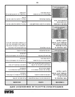
Страница 57: ...reno C sped mojado Corte el c sped una vez que se seque Corte lateral Cuchillas mal montadas disparejas Ajuste la inclinaci n y el nivel Cresta en el centro de la trayectoria de corte Cuchilla doblada...

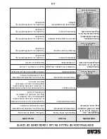
Страница 58: ...ado Cuchilla desafilada Afile la cuchilla CONDICI N IDENTIFICACI N DE FALLAS EN LAS CONDICIONES DE CORTE CAUSA SOLUCI N Salientes inclinadas Llantas con presi n desequilibrada Revise y ajuste la presi...

Страница 59: ...e las cuchillas Afile las cuchillas Bajas revoluciones RPM del motor Opere el motor a 3600 RPM Correa patinando Ajuste la tensi n de la correa C sped acumulado debajo de la Limpie la parte de abajo de...

Страница 60: ...operaci n reemplace el filtro de aceite del motor Despu s reemplace el filtro de aceite cada 100 horas de operaci n o cada mes lo que ocurra primero Consulte el manual del operador del motor para ins...

Страница 61: ...bitualmente la presencia de agua 2 Coloque un recipiente adecuado debajo del drenaje de aceite hidr ulico Quite la tapa del dep sito de aceite hidr ulico Retire la tapa de drenaje del accesorio en T u...

Страница 62: ...emento del filtro de aire Vea el manual del operador del motor X Engrase los rodamientos de la rueda loca Grasa de chasis X Verifique que toda la torniller a est bien ajustada Con mayor frecuencia si...

Страница 63: ...el tope de la barra del mango las palancas de freno en el conjunto soldado del eje del freno est n contra los topes en la plataforma del motor 2 Ajuste la varilla del accionador de freno en cualquier...

Страница 64: ...ad que usar con m s frecuencia 2 Apriete las palancas de control de direcci n y libere el seguro neutral Libere lentamente las palancas de control de direcci n permitiendo que la m quina se mueva haci...

Страница 65: ...reloj justo hasta que la rueda gire hacia atr s Anote la posici n de la tuerca de ajuste Para ajuste neutral divida la diferencia entre las dos posiciones anotadas de la tuerca de ajuste Repita el pro...

Страница 66: ...s diferentes para el desempe o ptimo A Posici n 3 el deflector se instala usando el conjunto superior de agujeros en el deflector frontal soldado dentro de la plataforma de corte Vea la Figura 6 p gin...

Страница 67: ...e servicio realizados en la plataforma siga el siguiente procedimiento Vea la Figura 3 p gina 11 1 Apague el motor y retire la llave 2 Soporte la plataforma con cuatro bloques tendr que retirar las ho...

Страница 68: ...RSE apriete ambas palancas bloquee los seguros de neutral y mueva la palanca de ajuste de velocidad a neutral NOTA S lo se recomienda la velocidad m xima para transporte 6 Libere el freno de estaciona...

Страница 69: ...r de operar esta m quina 2 Antes de arrancar el motor Revise el nivel de aceite en el motor y en el dep sito hidr ulico NOTA Use gasolina con un octanaje no menor de 87 y un m ximo de 10 de Etanol Lle...

Страница 70: ...r ajuste limpieza o reparaci n 3 Nunca realice ajustes a la m quina con el motor en operaci n a menos que se le indique espec ficamente hacerlo as Si el motor est funcionando mantenga las manos los pi...

Страница 71: ...a y corte lentamente NO use la mano para desatascar la tolva de descarga Use una varilla u otro dispositivo para retirar el material atascado despu s de apagar el motor y que las cuchillas paren de gi...

Страница 72: ...la cuchilla a la posici n OFF aplique el freno de estacionamiento y mueva los seguros de neutral a neutral 9 Siempre debe estar instalada la tolva de descarga y en la posici n baja en la plataforma de...

Страница 73: ...dad localizados en las calcoman as del equipo y por todo este manual El mensaje que sigue al s mbolo contiene informaci n importante sobre seguridad Para evitar posibles lesiones o la muerte lea detal...

Страница 74: ...o b sico Elemento cortante Desconectar Continuamente variable Lineal Lea el manual del operador Peligro de objetos lanzados Mantenga alejados a los curiosos Punto de contacto 481039S S MBOLO DESCRIPCI...

Страница 75: ...si n Ahogador Encendido Arranque Tensi n del resorte en la polea Aceite Apagado Parada S MBOLO DESCRIPCI N S MBOLO DESCRIPCI N S mbolos ISO Cuchilla giratoria 48071S Freno de estacionamiento Riesgo de...

Страница 76: ...LO USE DISPOSITIVOS DE CONDUCCI N APROBADOS POR SCAG LEA EL MANUAL DEL OPERADOR 481109 SP ADVERTENCIA INTRODUCCI N Su cortac sped se fabric seg n las normas m s exigentes de la industria Sin embargo...

Страница 77: ...rma de corte SWMU 36 24 25 Plataformas de corte SWMU 48 y 52 26 27 Bastidor de plataforma de corte de 36 28 29 Bastidor de plataforma de corte de 48 y 52 30 31 Plataforma del motor 32 33 Componentes d...

Страница 78: ...ento y almacenamiento 7 8 Procedimientos de arranque inicial 8 Operaci n del cortac sped 8 9 Tensi n de la correa 9 Ajustes de la plataforma de corte 10 11 Cuchillas de corte 11 Ajuste del deflector d...

Страница 79: ...asca detenga el motor antes de limpiar Mantenga las manos los pies y la ropa lejos de las partes m viles Lea este manual completamente as como cualquier otro manual proporcionado con su cortac sped Ma...

Страница 80: ...DE SEGURIDAD PARA SU CORTAC SPED SCAG LA LECTURA DE ESTE MANUAL LE PUEDE AYUDAR EN EL MANTENIMIENTO Y LOS PROCEDIMIENTOS DE AJUSTE A FIN DE MANTENER SU CORTAC SPED TRABAJANDO A LA M XIMA EFICIENCIA L...

Отзывы: