13
STEERING CONTROL ROD
ADJUSTMENT
-NOTE-
This adjustment is made to allow the steering
control levers to be moved out of the neutral
latch without engaging reverse.
Before making this adjustment be sure that the
speed control bearing is just touching the speed
control cam and that the bellcrank bearing is
resting in the center groove of the neutral cam.
1. Remove the speed control spring. Remove the
steering control rod swivel hair pin. Check the
location of the swivel in the slotted hole in the bell
crank.
2. Turn the swivel joint on the steering control rods until
the swivel joint is centered in the slot in the bellcrank.
3. Reinstall the speed control spring onto the swivel.
Install the hair pin onto the swivel. (See Figure 10).
Figure 10. Control Rod Adjustment
SLO
W
FA
ST
TRA
CKING
ADJUSTME
NT
SEE OPERA
TOR'S
M
AN
UA
L
390s0198-1
TRACKING ADJUSTMENT
-NOTE-
Before proceeding with this adjustment, be sure
that the tire pressures are correct, (see page 8)
and that the neutral adjustment and the steering
control rod adjustment have been completed.
1. With the machine on a flat level surface, start the
engine and place the speed adjustment lever into the
speed that will most often be used.
2. Squeeze the steering control levers and release the
neutral latch. Slowly release the steering control
levers, allowing the machine to move forward.
WARNING:
BEFORE ATTEMPTING TO MAKE ANY TRACKING
ADJUSTMENTS:
1. Move the speed adjustment lever to the
neutral position.
2. Place the blade engagement switch in the
OFF position.
3. Apply the parking brake.
4. Move the steering control levers into the
neutral position.
3. If the machine pulls to one side, stop the mower by
placing the steering control levers in the neutral
position. Using the adjustment wrench located on the
left side of the machine, turn the tracking adjustment
nut on the slower side counter clockwise until the
machine tracks straight. (See Figure 11, Page 14).
4. Bring the steering control levers back to the neutral
lock position and check to see that the machine does
not creep forward on the adjusted wheel.
5. If the machine creeps in neutral you have moved out
of the neutral band and will have to turn the tracking
adjustment nut clockwise until the machine does not
creep.
6. Repeat steps 1 and 2. If the machine continues to
pull to one side, stop the mower by placing the
steering control levers in the neutral position. Turn
the tracking adjustment nut on the faster side clock-
wise until the machine tracks straight.
7. If tracking cannot be achieved, contact your Scag
servicing dealer.
Содержание SCAG POWER EQUIPMENT SWZU Series
Страница 27: ...23 NOTES...
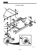
Страница 32: ...28 36A DECK FRAME 1 2 3 4 5 4 7 7 8 9 10 11 12 13 14 15 23 19 16 22 SWZU06DF36 24 25 6 25 6 17 18 20 21 17...
Страница 47: ...43 WIRE HARNESS ADAPTER PART NO 481717 KAWASAKI 16 HP 17 HP 19HP SWZU06WH481717...
Страница 49: ...45 REPLACEMENT DECALS AND INFORMATION PLATES 11 482297 13 FAST SLOW PARKING BRAKE OFF ON 10 12 SWZU 481906 9...
Страница 51: ...47 NOTES...
Страница 54: ...2 3 NOTAS...


