


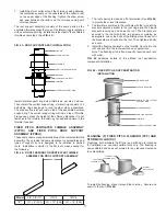
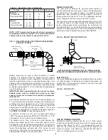

FIG. 43 - ROOF SUPPORT ASSY. INSTALLATION
Install lateral support ring below thimble as per step 4 above.
Then install the vertical support ring. Vertical ring consists of 2
half-clamp rings designed to lock together when assembled.
The pipe section joint will rest on top of the assembled vertical
support ring. The vertical support ring will rest on top of Thimble
Flange and carries the weight of the chimney. Because it is not
fastened to the thimble, the chimney can expand upward in the
thimble if needed.
FIXED PITCH VENTILATED THIMBLE ASSEMBLY
(FPVTA) AND FIXED PITCH ROOF SUPPORT
ASSEMBLY (FPRSA)
These components are special variations of the ventilated thimble
assembly. They provide the same clearance to combustibles and
types of support, but are designed to be installed in pitched
roofs. Installation is similar to the flat roof versions except for
the following.
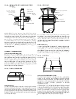
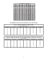
FIG. 44 – ROOF FRAMING FOR VENTILATED THIMBLE
ASSEMBLY OR ROOF SUPPORT ASSEMBLY
1. The roof opening is sized as a flat projection (See
FIG. 44
)
to provide the correct clearance.
2. The thimble is centered in the roof hole with the two pivoting
brackets oriented parallel to the roof ridge and the hinged
brackets running up and down the roof. The brackets are
secured to the roof with bolts, lag screws or welding as
appropriate. Leave the bolts of the sliding mount loose until
the brackets are attached to the roof. Then tighten all bolts
and nuts.
3. Install the flashing centered on the thimble. Secure it to the
roof and seal it to the roof membrane as appropriate.
Note: The flashing pitch is fixed, specify required pitch rate
with order.
FIG. 45
illustrates details of the pitched roof penetration
component installation.
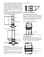
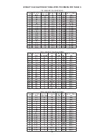
FIG. 45 – FIXED PITCH ROOF PENETRATION
INSTALLATION
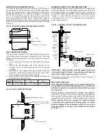
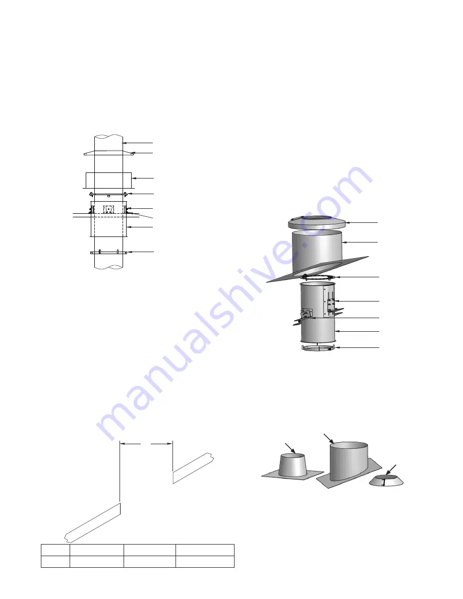
FLASHING (F) FIXED PITCH FLASHING (FPF) AND
STORM COLLAR (SC)
Flashings, both standard (Tall Cone) and pitched, are intended
for installation on non-combustible roofs only. The flashing is
non-ventilated and does not provide for any reduced clearance
to combustibles.
PIPE O.D.
STORM COLLAR
FLASHING
VERTICAL SUPPORT RING
BRACKET
LAG SCREW OR BOLT
THIMBLE
LATERAL SUPPORT RING
“X”
STORM COLLAR
PITCHED FLASHING
VERTICAL OR LATERAL
SUPPORT RING
HINGED BRACKET
PIVOTING BRACKET
THIMBLE
LATERAL SUPPORT RING
17
TALL CONE
FLASHING (F)
FIXED PITCH
FLASHING (FPF)
STORM
COLLAR (SC)
7. Install the storm collar around the chimney casing allowing
the ventilation spacers on the underside of the collar to rest
on the upper edge of the flashing. Tighten the draw screw
and seal between the collar and the chimney casing with
chimney sealant.
The roof support assembly consists of the same parts as the
ventilated thimble except that one of the lateral rings is replaced
with a vertical support ring. Installation is identical to the ventilated
thimble except step 4 (See
FIG. 43
).
Model
PIC & IPIC-1
IPIC-2
IPIC-4
“X”
I.D. + 8” (203) I.D. + 10” (254)
I.D. + 14” (356)
To install the flashing, place it around the chimney. Secure and
seal it to the roof (
FIG. 46
).