


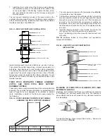


FIG. 40 – STACK SUPPORT ASSEMBLY INSTALLATION
VENTILATED THIMBLE ASSEMBLY (VTA) AND ROOF
SUPPORT ASSEMBLY (RSA)
The ventilated thimble assembly is designed to allow Model
PIC/IPIC chimney to penetrate a combustible roof at a nominal
3” clearance to combustibles.
FIG. 41
illustrates the required
minimum framing dimensions. The ventilated thimble is intended
for installation on a flat roof. It may be used on a pitched roof if a
curb is installed at the penetration to provide a level surface for
mounting the thimble.
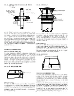
FIG. 41 – ROOF FRAMING FOR VENTILATED THIMBLE
ASSEMBLY OR ROOF SUPPORT ASSEMBLY
Model
PIC & IPIC-1
IPIC-2
IPIC-4
“X”
I.D. + 8” (203) I.D. + 10” (254)
I.D. + 14” (356)
The roof support assembly is a special variation of the ventilated
thimble which also provides vertical support to the chimney. It is
especially useful when the chimney rise below the roof is long
enough to cause movement from thermal expansion to exceed
approximately 2” (51).
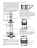
The ventilated thimble consists of the thimble with 4 support
brackets; 2 lateral support rings, split for ease of installation; a
flashing; a storm collar.
Installation of the ventilated thimble is as follows (See
FIG. 42
):
1. Cut the roof opening and reinforce the edges of the hole
as appropriate for the expected load bearing requirements.
Attach the thimble brackets to the thimble using the
hardware provided.
2. Set the thimble through the roof, making sure it is centered
in the roof penetration hole, and secure it to the roof deck
with bolts or lag screws supplied. The brackets may be
welded to a metal roof, if desired.
3. Install the chimney passing through the thimble and
extending above the roof.
4. Install the 2 split lateral support rings on the chimney casing,
one above the thimble and one below the thimble. Leave
the bolts loose enough to allow the ring to slide along the
casing. The spacer tabs are to be toward the thimble.
5. Push the lateral rings along the chimney casing until they
are completely enclosed in the thimble.
6. Install the flashing centered on the thimble. Secure it to the
roof and seal it to the roof membrane as appropriate.
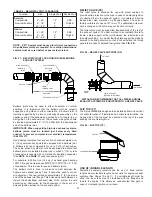
FIG. 42 - VENTILATED THIMBLE ASSY. INSTALLATION
“X”
“X”
16
EXIT CONE
FULL ANGLE RING
BRACING (BY OTHERS)
NOTE: DO NOT USE VARIABLE LENGTH OR
EXPANSION JOINT BETWEEN BREECHING &
STACK SUPPORT ASSY.
STACK SUPPORT ASSEMBLY
CONCRETE PAD OR
STRUCTURAL BASE
BREECHING
90° TEE
LATERAL SUPPORT RING
FLASHING
STORM COLLAR
SUPPORT BRACKET
THIMBLE
LATERAL SUPPORT RING
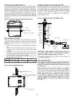
STACK SUPPORT ASSEMBLY (SSA)
The stack support assembly is intended for use as a base mount
for mounting the stack on a concrete floor or a structural steel
stand. It is equipped with a predrilled steel baseplate for the
insertion of anchor bolts or studs. A 9-inch section of pipe is
attached to the baseplate and contains a false bottom 4½” (114)
above the floor. A 1” (25) NPT nipple extends through the side of
the pipe section just above the false bottom to allow drainage of
rain or condensate (See
FIG. 39
). It is recommended that a 90º
manifold tee with a cleanout cap be installed above the stack
support to provide access to the stack.
When using a stack support assembly as the stack base, it is
important to use exact pipe lengths to raise the stack height to
the breeching connection point (See
FIG. 40
). Use of variable
lengths or expansion joints in the stack under the breeching
connection defeats the purpose of the stack support assembly.
These components will not support weight.
FIG. 39 – STACK SUPPORT ASSEMBLY
1” N.P.T. NIPPLE