


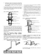


FIG. 28 – PLATE SUPPORT BRACING REQUIREMENTS
“X” is a minimum of 30° when bracing is used. A welded frame
must be adequately attached to structural member for framework
rigidity if bracing isn’t used.
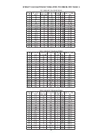
Pipe
Diameter
PS Plate
Thickness
Bracing for (PS) Plate Support
Height of Stack
50’ (15.24m) 100’ (30.48m)
6” - 20”
3/16” (5)
1 1/4”x1 1/4”x1/8”
(32x32x3)
2”x2”x1/4”
(51x51x6)
22” - 36”
1/4” (6)
2”x2”x1/8”
(51x51x3)
3”x3”x1/4”
(76x76x6)
38” - 48”
1/4” (6)
3” (76) channel: 3”x1 1/2”x1/4”
(76x38x6)
Pipe
Diameter
PS Plate
Thickness
Framework for (PS) Plate Support
Height of Stack
50’ (15.24m) 100’ (30.48m)
6” - 20”
3/16” (5)
1 3/4”x1 3/4”x1/8”
(44x44x3)
3”x2”x3/16”
(76x51x5)
22” - 36”
1/4” (6)
2”x2”x1/4”
(51x51x6)
4”x3”x1/4”
(102x76x6)
38” - 48”
1/4” (6)
3” channel: 3”x1 1/2”x1/4”
(76x38x6)
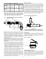
When the supported section is subject to thermal expansion
or is in a vertical position, so that the plate support is weight
bearing, the support structure must be braced with diagonal
members or gussets to prevent deflection of the supported joint
(See
FIG. 28
). Plate supports are usually located adjacent
to fittings, such as tees or elbows, to protect the fitting from
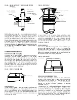
expansion stresses. Chimneys heights in excess of a single
plate support capability can be resupported with additional plate
support(s). An expansion joint must be used between support
points (See
FIG. 29
).
FIG. 29 – RESUPPORT REQUIREMENTS
A plate support assembly is to be attached only to
non-combustible construction such as block, concrete or steel
with clearance that is adequate for installation and access.
DO NOT ATTACH THE PLATE SUPPORT TO COMBUSTIBLE
CONSTRUCTION.
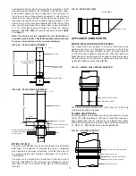
For maximum support, the entire perimeter of the plate support
assembly must be attached to structural framing (See
FIG. 30
).
Structural members are supplied by the installer.
FIG. 30 – SECTIONAL DETAIL FOR PLATE SUPPORT
PLATE SUPPORT
EXPANSION JOINT
FULL ANGLE RINGS
PLATE SUPPORT
EXPANSION JOINT
FULL ANGLE RINGS
PLATE SUPPORT
TO APPLIANCE
DRAIN
TEE CAP
90° TEE
200 FT. (60.96M)
MAXIMUM
100 FT.
(30.5M)
FLUE
CASING
FLANGE
BAND
CLAMP
RING
PLATE
13
STRUCTURAL BRACING
(BY OTHERS)
PLATE SUPPORT
CLAMP RING
BRACING
(BY OTHERS)
“X”
PIPE SECTION
PIPE SECTION
EXHAUST
FLOW
PLATE SUPPORT (PS)
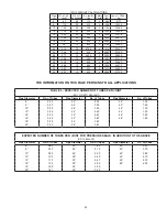
NOTE: See TABLE 5 for maximum supported height.
The plate support assembly is designed to provide maximal
support to vertical sections and to provide fixed-point support for
horizontal sections. The plate support must be attached to the
building structure or support with rigid structural members.
NOTE:
Clamp ring sections and plate sections install at
90° angles.