


SQA-Vision
Service Manual Version 109.13.4
Edition rev.: Jan 2020
14
Close the SQA-Vision. Reconnect the power cord and
turn the unit back on. If the problem persists -
Contact Customers Support
Power Inlet
Notes:
1.
Turn off the
On/Off switch and
disconnect the
power cord from
the SQA-Vision
before opening.
2. Refer to the
Appendix section
for a flow chart of
power supply
problems and
solutions.
Power Inlet (Part# VS-E-00850-00)
ISSUE:
There is no voltage supplied to the PSU from the inlet.
Open the SQA-Vision.
Unscrew the power-inlet screws at the rear panel of the device.
Disconnect the power supply connector from the power supply board.
Gently pull the rubber cover of the power inlet until the connectors are exposed.
Please note how all connector are connected to the power inlet.
Disconnect all connectors from the power inlet.
Gently pull the power inlet out of the SQA-Vision through the rear panel.
Insert a new power inlet and re-connect the cables.
Re-connect the internal cables, re-place the internal cover and re-connect the power
supply cable to the power supply board.
Fan Assembly
Fan Assembly (part # V-H-00575-00)
ISSUE:
The master switch is
ON
, the power indicator is lit but the fan is not rotating
Open the SQA-Vision.
Confirm that all the fan connecting cables are in place.
Check that the voltage in the main board connector of
the fan (location JP1) is:
0V: black wire
+12V: purple wire
If no power is evident, replace the main PSU (see
previous section)
If the voltage is as described above, replace the fan:
Unscrew the four fan screws.
Replace the fan assembly (fan + cable).
Re-connect the cables and screw the new fan to the rear panel of the SQA-Vision.
Do not change the direction of the outlet air flow! (the arrow on the fan should point
outwards)
Fan Assembly
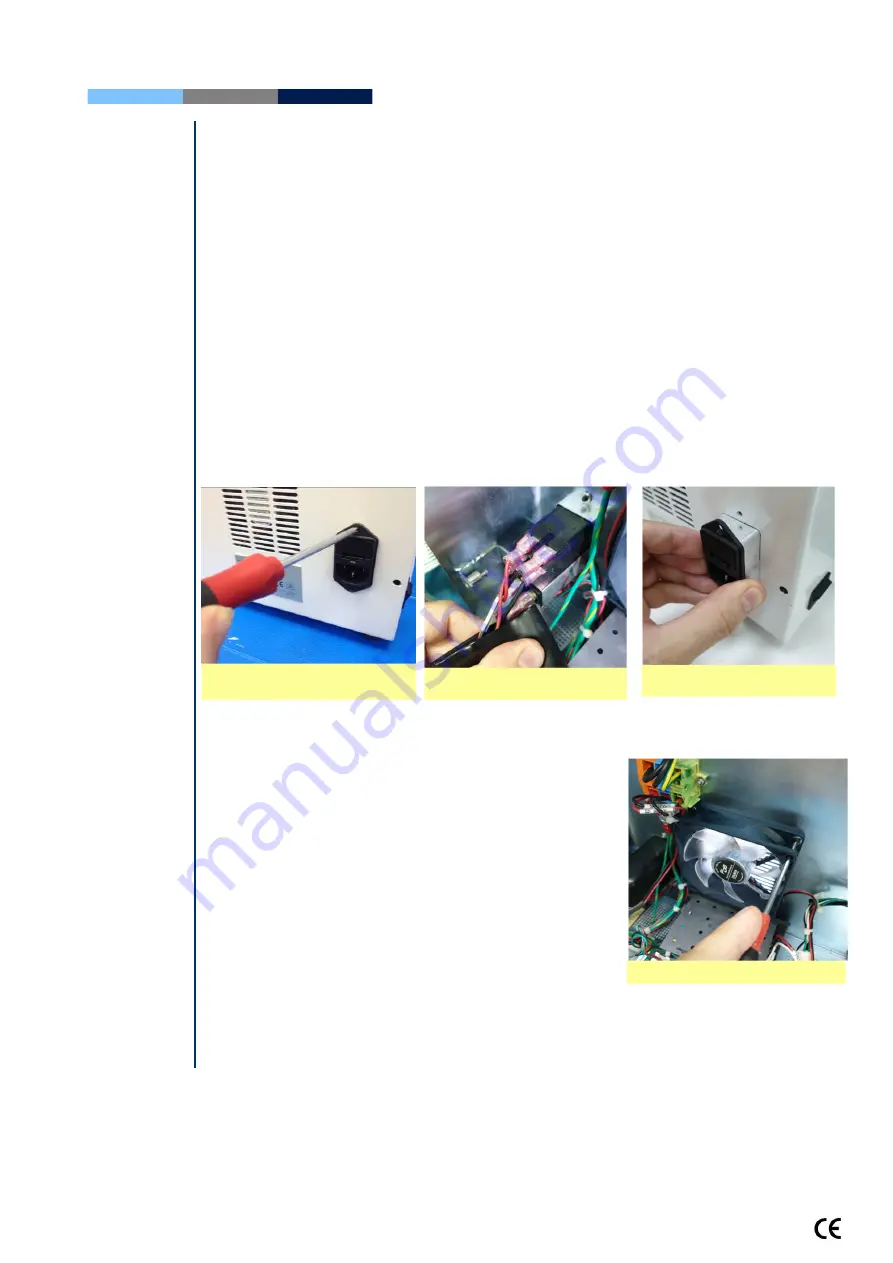
Gently pull the power inlet
from the rear panel
Unscrew the power inlet
screws
Gently pull the rubber cover


