


8-6
10 July 1998
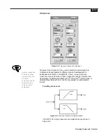
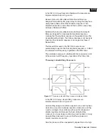
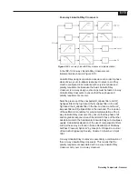
2.5 dB below the input level at the threshold. The divergence
continues to increase gradually until approximately 6 dB above
the threshold, beyond which the output level rise is dictated
solely by the selected compression ratio. There is a smooth,
gradual transition from no compression below the threshold to
compression above.
The sonic differences between the two knee types are often
subtle and are very much signal-dependent. Experimentation is
recommended.
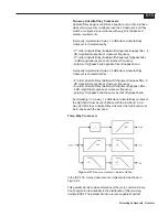
Sidechain Source
There are situations in which compression is applied to one
channel based upon the level in another channel. This might be
used in a stereo signal pair to prevent image shift; one of the
channels would be considered to be the level reference and the
compressors in both channels would be set up identically.
Another example might be ducking, where the compression
applied to background music in one channel would be controlled
by the level of the announcer’s voice in another.
The Sidechain Source channel selection indicates the channel
whose level is to be used to control the compressor. If the input
channel is to control itself, then it should be selected as the
Sidechain Source. Otherwise the appropriate other channel
should be selected from the set of available Sidechain Sources
in the menu.
Unfamiliar Controls
There are two controls on the ISP-100 compressor that are not
available in traditional dynamic range compressors. These controls
provide much greater flexibility and utility to this compressor than
can be achieved with traditional compressors.
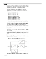
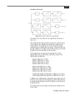
Detection Window
The detection window is the period of time over which the
compressor computes the average signal level. Every dynamic
range compressor that operates upon average signal level uses
a detection window. In traditional compressors this window is of
fixed length, and the operator may not even be aware of that
length.
Some traditional compressors provide switching between
average and peak detection. This is actually just a selection
between a relatively long detection window of generally a few
tens or hundreds of milliseconds, and a very short detection
window of generally a few tens or hundreds of microseconds.
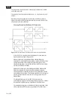
The ISP-100 compressor provides for operator control of the
length of the detection window. Very dynamic signals and
signals containing a lot of high frequency energy require shorter
detection windows. Non-dynamic signals and signals containing
mostly low frequency energy require longer detection windows.
Detection Window is adjustable in the range 20
µ
Sec (one
sample) to 5 Sec.
Содержание Integrated Signal Processor ISP-100
Страница 1: ...User s Manual ISP 100 INTEGRATED SIGNAL PROCESSOR...
Страница 2: ...THIS PAGE LEFT BLANK INTENTIONALLY...
Страница 24: ...2 10 10 July 1998 THIS PAGE LEFT BLANK INTENTIONALLY...
Страница 32: ...3 8 10 July 1998 THIS PAGE LEFT BLANK INTENTIONALLY...
Страница 48: ...5 6 10 July 1998 THIS PAGE LEFT BLANK INTENTIONALLY...
Страница 126: ...A 4 10 July 1998 THIS PAGE LEFT BLANK INTENTIONALLY...
Страница 128: ...B 2 10 July 1998 MONDOEQ QMS...
Страница 129: ...B 3 Standard QuickMAPs 2X6CMBC QMS...
Страница 130: ...B 4 10 July 1998 2X8COMB QMS...
Страница 131: ...B 5 Standard QuickMAPs 3X6CMBC QMS...
Страница 132: ...B 6 10 July 1998 2X8THRU QMS...
Страница 133: ...B 7 Standard QuickMAPs 4CHAN QMS...
Страница 134: ...B 8 10 July 1998 4X6CMBC QMS...
Страница 135: ...B 9 Standard QuickMAPs 4X6THRU QMS...
Страница 136: ...B 10 10 July 1998 3_2W QMS...
Страница 137: ...B 11 Standard QuickMAPs 2WAYS QMS...
Страница 138: ...B 12 10 July 1998 2_3WAY QMS...
Страница 139: ...B 13 Standard QuickMAPs 2_2W_SUB QMS...
Страница 140: ...B 14 10 July 1998 2_2W_FR QMS...
Страница 141: ...B 15 Standard QuickMAPs 2_2W_2ST QMS...
Страница 142: ...B 16 10 July 1998 4_2WAYS QMS...
Страница 143: ...B 17 Standard QuickMAPs 4W_2FR QMS...
Страница 144: ...B 18 10 July 1998 LCR QMS...
Страница 145: ...B 19 Standard QuickMAPs MONO3W QMS...


