


8-40
10 June 1998
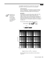
to 0 dB and its polarity to positive (in-phase). Bypassing in a muted
channel un-mutes it.
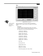
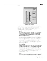
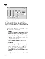
Metering
The meter located at the left of the component measures level in
dBFS. The meter’s level will turn red 3 dB before clipping. The red
clip light is located at the top of the meter. The green signal present
light is located at the bottom of the meter.
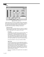
Master Attenuator
The Master Attenuator can be adjusted three ways:
Using the Slider
Click on the indicator on the slider and while continuing to hold
down the mouse button, move the mouse up and down. The
numbers in the box below the slider will change. When the
desired level is reached, release the mouse button.
Using the Text Box
Click in the box. Using the Back Space and/or Delete keys
erases the current entry and enters the new level. Be sure to
press the Enter key after the entry is made. Clicking outside the
text box without pressing the Enter key will cause the setting to
return to the number that it was before a change was attempted.
Alternatively, click and drag across the number in the box to
highlight the number in it. Type the new setting and press the
Enter key when finished.
Using the UP/DOWN Arrows
To increase the level, click on the up arrow. To decrease the
level attenuation, click on the down arrow. The amount of
increase or decrease is controlled by the fine/coarse control.
Fine or Coarse Control
This button determines the increment/decrement associated with the
UP/DOWN arrows. Fine produces small steps in value, while Coarse
provides large steps in value. Clicking on the button will toggle the
setting.
Polarity Control (+/-)
This button determines the polarity of the signal. A + indicates that
the signal will not have it’s phase altered. A - indicates that the
signal’s phase will be changed 180°. Clicking on the button will
toggle the setting.
Mute Control
This button determines if the input signal will be muted. A gray LED
indicates that the signal is not muted, while a red LED indicates that
the signal is muted. Clicking on the button will toggle the setting.
Pre-Fader Metering (PFM)
This button determines if the meter is getting its data pre- or post-
fader. A gray LED indicates that the meter information is post-fader
Содержание Integrated Signal Processor ISP-100
Страница 1: ...User s Manual ISP 100 INTEGRATED SIGNAL PROCESSOR...
Страница 2: ...THIS PAGE LEFT BLANK INTENTIONALLY...
Страница 24: ...2 10 10 July 1998 THIS PAGE LEFT BLANK INTENTIONALLY...
Страница 32: ...3 8 10 July 1998 THIS PAGE LEFT BLANK INTENTIONALLY...
Страница 48: ...5 6 10 July 1998 THIS PAGE LEFT BLANK INTENTIONALLY...
Страница 126: ...A 4 10 July 1998 THIS PAGE LEFT BLANK INTENTIONALLY...
Страница 128: ...B 2 10 July 1998 MONDOEQ QMS...
Страница 129: ...B 3 Standard QuickMAPs 2X6CMBC QMS...
Страница 130: ...B 4 10 July 1998 2X8COMB QMS...
Страница 131: ...B 5 Standard QuickMAPs 3X6CMBC QMS...
Страница 132: ...B 6 10 July 1998 2X8THRU QMS...
Страница 133: ...B 7 Standard QuickMAPs 4CHAN QMS...
Страница 134: ...B 8 10 July 1998 4X6CMBC QMS...
Страница 135: ...B 9 Standard QuickMAPs 4X6THRU QMS...
Страница 136: ...B 10 10 July 1998 3_2W QMS...
Страница 137: ...B 11 Standard QuickMAPs 2WAYS QMS...
Страница 138: ...B 12 10 July 1998 2_3WAY QMS...
Страница 139: ...B 13 Standard QuickMAPs 2_2W_SUB QMS...
Страница 140: ...B 14 10 July 1998 2_2W_FR QMS...
Страница 141: ...B 15 Standard QuickMAPs 2_2W_2ST QMS...
Страница 142: ...B 16 10 July 1998 4_2WAYS QMS...
Страница 143: ...B 17 Standard QuickMAPs 4W_2FR QMS...
Страница 144: ...B 18 10 July 1998 LCR QMS...
Страница 145: ...B 19 Standard QuickMAPs MONO3W QMS...


