1
\
1
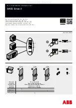
motor operator
m
remove the black cover
m
unscrew the fixing screw
m
rock the mechanism
[!]
connect wire leads to
termmals according to the
schematic diagram below :
- -.- ,...-.----------\-
I
·�
:�
:�set
- -
-+-
-----------
motor
optional
operator
overcurrent
trip swHch
note
:
schematic diagram using
resetting push-button for remote
resetting. For other diagrams refer
to technical manual
m
secure the motor operator
using the fixing screw and replace
black cover
caution
:
operate up and down
the manual operating handle to
engage the fork around the toggle
h
I
!
---
i
ti
wire exits
it
I
I I
i
I
I
wire
exits
...,_
shunt tnp
or
under-
voltage
trip
®
82 A4 A2
raa151
152
@)
auxiliary
sw1tches
®
wire
exits
',"-,
www
. ElectricalPartManuals
. com


