background image


Ring B 


Ring A 


Fig. 12-4 Loop Back Operation  


PX-2300M  


LLOOP

               TxA   RxB


PX-2300M  


RLOOP  

 PX-2300M 


RLOOP 

BER 

Tester 

Содержание 2300M Series

Страница 1: ...C PRODUCTS IN AUSTRALIA Messrs Meridian Technologies Inc of Elmont NY United States of America design and manufacture at their headquarters in Elmont near New York an extensive range of quality equipm...

Страница 2: ...al parameters If a parameter is exceeded a flashing light and audible alarm are activated at all modems Both primary and secondary rings are moni tored simultaneously by the network diagnostics If the...

Страница 3: ...5 125 62 5 125 Singlemode Laser 9 125 9 125 Optical Output dBm 15 16 3 3 Reciever Sensitivity dBm 30 30 33 33 Optical Budget dB 15 14 30 30 Wavelength nm 850 1300 1310 1550 Optical Connector ST SC ST...

Страница 4: ...diagnostics on two or more master modems The PC based Network Management system incorpo rates real time system diagnostics for monitoring various net work and modem parameters including but not limit...

Страница 5: ...e transmit Time Delay RS 232D RS 422A RS 485 2w 4w TTL Single Handshake RS 232 DC to 125 Kb s Async 10 9 10 max Data Rate 5 ms Physical Dimensions PX 2300R Weight Card No of Slots 160 mm 6 3 L 100 mm...

Страница 6: ...PX 2300 SELF HEALING RING MULTIDROP FIBER OPTIC MODEM User s Manual...

Страница 7: ...s 13 24 Antistreaming values 17 4 3 LCD contrast potentiometer PX 2300M only 18 5 0 INSTALLATION 19 5 1 Master Slave configuration 19 5 2 Modem addresses 19 5 3 Connection to the diagnostic computer 2...

Страница 8: ...eridian s SpectraSmart software that resides on a standard computer The modems regenerate fiber optic signals and provide greater system loss budgets and increased distance Wide temperature operating...

Страница 9: ...at each of the remote or slave locations Since the customer s data is asynchronous and not guaranteed to be present at all times Meridian uses its proprietary network control diagnostic signals to co...

Страница 10: ...ansion capabilities include the ability to drop add or repeat channels at any modem without signal degradation Commonly referred to as a counter rotating ring the self healing ring SHR architecture al...

Страница 11: ...ications around the ring 2 2 Self healing ring with Dual Master Self healing ring with Redundant Masters In a standard SHR with one master modem this single master modem can represent a single point f...

Страница 12: ...ntegrity of both master modems each of the slaves and the entire fiber network will be monitored and reported back to each of the modems and to the control center a feature unique to Meridian 3 0 DESC...

Страница 13: ...Rx A 14 LCD liquid crystal display 15 Optic port 1 transmit ring A Tx A and receive ring B Rx B 16 Jumpers 13 24 antistream value 17 DIP switch configuration mode selected 18 LEDs electrical optical s...

Страница 14: ...d by the internal diagnostics to properly identify and communicate with each modem Master modems can be set between 0 and 99 while each of the slave modems can be set from 1 to 99 there is no 0 for sl...

Страница 15: ...the modem to a standard Windows based computer for operating the SpectraSmart PC diagnostics An additional RS 485 RJ45 port is available for interconnecting master modems either in the same ring as a...

Страница 16: ...educed The termination resistors are 120ohm resistors are located inside the modem Termination resistors are not required for RS 232 applications 4 2 Jumpers 13 24 Antistreaming values In order to pre...

Страница 17: ...same diagnostic computer the interconnected master modems via the RS 485 bus must be numbered consecutively starting from 0 Please note that it is necessary to start with the number 0 for the master...

Страница 18: ...done with the use of the local and remote loop back testing in conjunction with a BERT test equipment unit The other is by using the PX 2300 s built in network diagnostic system 6 1 Loopback testing T...

Страница 19: ...temperature power supply voltages optical ring status alarm history software revision and various other parameters If one of the modem s operational parameters exceeds its critical level a flashing l...

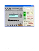
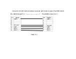
Страница 20: ...11 11 2006 15 Rev 2 0 Fig 6 2 Fig 6 3 Fig 6 4 Fig 6 5 Fig 6 6 Fig 6 7 Fig 6 7 Fig 6 8 Fig 6 9 Fig 6 10...

Страница 21: ...11 11 2006 16 Rev 2 0 Fig 6 11 Fig 6 12 Fig 6 13 Fig 6 14 Fig 6 15 Fig 6 16 Fig 6 17 Fig 6 18 Fig 6 19 Fig 6 20...

Страница 22: ...NMS 1 2 3 4 5 6 7 8 9 10 Fig 7 1 PX 2300R Front Panel Layout 1 DIP switch configuration mode selected 2 LEDs indicate the status of electrical and optical signal 3 Optic port B transmit line B TX B 4...

Страница 23: ...R this figure illustrates how to connect the diagnostics back to the computer either via the RS 232 or USB ports If more than one master PX 2300R modem is housed in the same chassis the diagnostic inf...

Страница 24: ...ll then discover and identify the PX 2300R as a Master module in a ring or string configuration depending on module switch settings Fig 7 3 SpectraSmart Diagnostic Interface from PX 2300R to Computer...

Страница 25: ...ing up Found New Hardware Wizard 3 Insert SpectraSmart installation CD and click Next 4 Click Search for a suitable driver for my device recommended select Next 5 Click CD ROM drive select Next 6 If t...

Страница 26: ...imultaneously monitors several rings and strings Recognizes multiple network faults Collects displays and monitors all operational parameters from each modem Records complete network alarm history Dis...

Страница 27: ...mode the user needs to enter the number of slaves and click OK This mode is important if the user suspects that the network may not have fiber continuity throughout the network 8 1 PC Display of Remot...

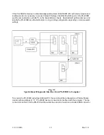
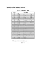
Страница 28: ...11 11 2006 23 Rev 2 0...

Страница 29: ...e devices Modem address is incorrect Optical cable connections are incorrect Check Master modem connection to diagnostic computer SpectraSmart program running but net ring or string is not activated M...

Страница 30: ...or 4 wire TTL 2 channels System Bit Error Rate 1 in 109 or better Visual Indicator 12 Status LED s for Alarm PWR A PWR B Master Link A Link B Diag A Diag B Data 1T Data 1R Data 2T Data 2R Dry Contact...

Страница 31: ...ranty and Meridian Technologies Inc at its option may first inspect such goods at the premises of the Buyer or may give written authorization to Buyer to return the goods to Meridian Technologies Meri...

Страница 32: ...32 IN 1 TD 3 RS 232 OUT 1 RD 4 RS 232 IN 2 RTS 5 RS 232 OUT 2 CTS 6 RS 232 OUT 3 DSR 7 GND 8 RS 232 OUT 4 CD 9 RS 485 IN 2 WIRE 10 RS 485 IN 2WIRE 11 RS 485 OUT 12 RS 485 OUT 13 GND 14 5V 15 TTL OUT 1...

Страница 33: ...ort RS 485 PX 2300M for Diagnostic Pin Configuration FRONT VIEW LEFT SIDE PIN 1 PIN NO Description 1 ISOLATED GROUND 2 XMT OUT 3 RCV IN 4 RCV IN 5 XMT OUT 6 ISOLATED GROUND Table 3 PIN NO Description...

Страница 34: ...32 PX 2300R for Diagnostic Pin Configuration FRONT VIEW LEFT SIDE PIN 1 Table 4 PIN NO Description 1 XMT OUT RS 485 2 RX IN RS 232 3 TX OUT RS 232 4 DSR IN RS 232 5 GROUND 6 XMT OUT RS 485 7 RCV IN RS...

Страница 35: ...Master Data Slave Data Slave Data Slave Data String B String A Fig 12 1 String Configuration Master 0 TxB RxA TxA RxB Slave 1 TxB RxA TxA RxB Slave N TxB RxA TxA RxB Slave 2 TxB RxA TxA RxB...

Страница 36: ...Master Data Slave Data Slave Data Slave Data Ring B Ring A Ring A Ring B Fig 12 2 Ring Configuration Master 0 TxB RxA TxA RxB Slave 1 TxB RxA TxA RxB Slave N TxB RxA TxA RxB Slave 2 TxB RxA TxA RxB...

Страница 37: ...Master Data Slave Data Slave Ring B Ring A Ring A Ring B Fig 12 3 Dual Master Ring Configuration Primary Master 0 TxB RxA TxA RxB Secondary Master 0 TxB RxA TxA RxB Slave N TxB RxA TxA RxB Slave 1 TxB...

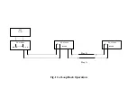
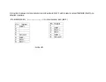
Страница 38: ...Ring B Ring A Fig 12 4 Loop Back Operation PX 2300M LLOOP TxA RxB PX 2300M RLOOP PX 2300M RLOOP BER Tester...

Страница 39: ...S 5 out2 CTS 1 GND 3A 4A DCE 3B 4B DTE RS 232 2 channels without handshake 4 1 ch 2 in1 TD 3 out1 RD 1 GND 2 ch 4 in2 TD 5 out2 RD 7 GND RS 485 2 wire 6 9 in 10 in 0 13 GND 11 RS 485 4 wire 7 9 in 10...

Страница 40: ...PC port RS 232 DB9 and Master module PX 2300M R RJ45 PC PX 2300 Cable 1 Pin Signal 1 2 RD in 3 TD out 4 DTR out 5 Ground 6 7 8 9 Pin Signal 1 2 TD out 3 RD in 4 DTR 5 Ground 6 7 8...

Страница 41: ...485 interface between subracks with master modules PX 2300R RJ45 PX 2300R Subrack x PX 2300R Subrack x 1 Cable 2 Pin Signal 1 XMT 2 3 4 5 Ground 6 XMT 7 RCV 8 RCV Pin Signal 1 XMT 2 3 4 5 Ground 6 XM...

Страница 42: ...nication card of subrack RJ11 with master module PX2300R RJ45 via RS 485 interface PX 2300R RJ45 Communication card RJ11 Cable 3 Pin Signal 1 XMT 2 3 4 5 Ground 6 XMT 7 RCV 8 RCV Pin Signal 1 2 XMT 3...

Страница 43: ...e Trademarks Windows is a registered trademark of Microsoft Corporation PICmicro is a registered trademark of Microchip Technologies Inc XILINX is a registered trademark of Xilinx Inc Company Address...

Страница 44: ......

Страница 45: ...mmunications Labelling Customer Equipment and Customer Cabling Notice 2001 made under section 407 of the Australian Telecommunications Act 1997 Instructions for completion Do not return this form to t...

Страница 46: ...mber and if applicable number of the test report Refer enquiries to manufacturer Messrs Meridian Technologies Inc 700 Elmont Road ELMONT NY 11003 United States of America Declaration I hereby declare...

Отзывы: