11/11/2006
20 Rev 2.0
7.1 PX-2300R Jumper Setting:
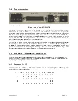
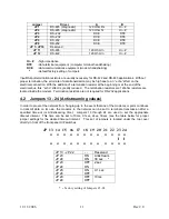
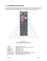
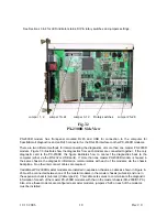
The function of the jumpers in the PX-2300R as identified in Figure 7-2 are identical to the jumpers on the
PX-2300M surface mount modem.
Refer to Section 4.0 for more information regarding the jumper settings. They are the same as in the PX-
2300M module, with the exception of Jumpers 1 & 2. These jumpers are located on another section of
the circuit board.
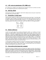
JP1
– RS-485 (diagnostic) – 120 ohm Rx
o--o o o o--o
Hi-Z *
JP2
– RS-485 (diagnostic) – 120 ohm Tx
o o--o o--o o
120 Ohm
* - default factory setting of Jumpers 1, 2
7.2 USB Port Configuration
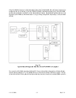
If you are going to connect the diagnostic computer to the PX-2300R USB port, please following these
instructions for proper installation of the USB drivers (FTDI Virtual COM Port - VCP):
1. Turn power on the Subrack and PC;
2. Plug in the USB cable. This should bring up Found New Hardware Wizard;
3. Insert SpectraSmart installation CD and click Next;
4. Click “Search for a suitable driver for my device(recommended)”, select Next;
5. Click CD-ROM drive, select Next;
6. If the Wizard found the driver, click Next, then Finish.
7. If the Wizard did not find the driver, click Back, then click “Specify a location” , then Browse
and find folder ‘Drivers’ on CD-ROM drive (usually D: or E:), select Next;
8. If the Wizard found the driver, click Next, then Finish.
If SpectraSmart had been in use previously with the RS-232 port & driver, it will be necessary to
change the Port in PC Registry. DO NOT TURN OFF THE SUBRACK. In the computer click Start
-> Settings -> Control Panel -> System ->Hardware -> Device Manager. Click + near Ports. In
the list under Ports find USB (COMX), where X is number of virtual COM Port. Usually it is
COM3 or COM4.
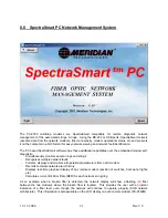
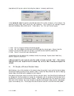
Start SpectraSmart PC program. When the Copyright screen appears click “Ctrl+P”. A “Choose
Port #” window will come up. Select the “X COM Port”, captured by USB that was previously
identified and click ‘OK’.
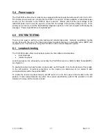
J1 J2
J1 J2
Содержание 2300M Series
Страница 6: ...PX 2300 SELF HEALING RING MULTIDROP FIBER OPTIC MODEM User s Manual...
Страница 20: ...11 11 2006 15 Rev 2 0 Fig 6 2 Fig 6 3 Fig 6 4 Fig 6 5 Fig 6 6 Fig 6 7 Fig 6 7 Fig 6 8 Fig 6 9 Fig 6 10...
Страница 21: ...11 11 2006 16 Rev 2 0 Fig 6 11 Fig 6 12 Fig 6 13 Fig 6 14 Fig 6 15 Fig 6 16 Fig 6 17 Fig 6 18 Fig 6 19 Fig 6 20...
Страница 28: ...11 11 2006 23 Rev 2 0...
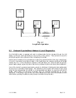
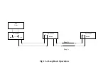
Страница 38: ...Ring B Ring A Fig 12 4 Loop Back Operation PX 2300M LLOOP TxA RxB PX 2300M RLOOP PX 2300M RLOOP BER Tester...
Страница 44: ......

