11/11/2006
12 Rev 2.0
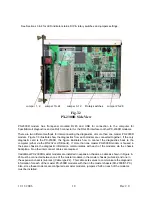
4.3 LCD contrast potentiometer (PX-2300M only)
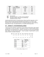
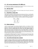
The contrast of the LCD display can be adjusted by the potentiometer located on the left side near button
#1. It is accessible through the hole on the left side of the modem.
5.0 INSTALLATION
Following these instructions, the installation of the PX-2300 relatively simple and requires no adjustments
and a minimal amount of switch settings.
5.1 Master/Slave configuration
Unless otherwise requested, all modems are shipped from the factory set as Slaves. To set the modem
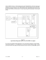
to the ‘Master’ mode of operation, the DIP switch on the front panel must be moved from the ‘Slave’ to
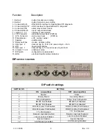
the ‘Master’ position (see the appropriate table in Section 3.1). For PX-2300M firmware version 3.12
and earlier , if the Master modem is connected to a computer for diagnostic purposes, it is necessary to
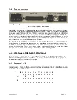
remove the modem cover and set the 3-pin jumper near the ‘menu‘ button # 1 to the opposite position.
Slave Master
5.2 Modem addresses
In order for the system diagnostics to properly interrogate the modems, it is necessary to set each
modem to its proper address. Master and Slave modems can be set from 0 to 99 and 1 to 99,
respectively. This is done by setting the three rotary switches on the front of the modem as mentioned in
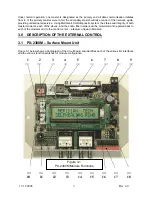
Section 3.2.
In the case of multiple strings or rings connected to the same diagnostic computer, the
interconnected master modems (via the RS-485 bus) must be numbered consecutively starting from ‘0’.
Please note that it is necessary to start with the number ‘0’ for the master modems. In a network with
dual master modems (primary and secondary) both master modem addresses must be set to the same
address
.
Slave modem addresses must begin with address #1 in both ring & string networks. These
slave modem addresses should be consecutively addressed starting from the master and going in the
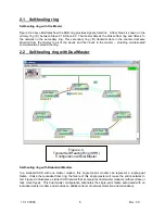
clockwise direction around a typical ‘ring’ network (see Fig.2).
In a string network the Master modem does not need to be located at one end of the string and, if fact,
can be located at any convenient place in the network. It is not recommended to use multiple master
(primary & secondary) modems in a string network. Slave numbering should continue on the left side of
the network (starting with the modem closest to the master).
5.3 Connection to the diagnostic computer
As previously mentioned, the Master modem is connected to the diagnostic computer via the RS-232 or
USB ports on the surface mount modems (PX-2300M).
Rings with both primary and secondary Master
modems use the RS-485 connector to interconnect these master modems together. Only the primary
Master modem needs to be connected to the diagnostic computer. Diagnostic communication will then
be through the Primary Master modem only. The PX-2300M modem (surface mount) and the PX-2300R
modem used either USB or RS-232 ports for connection to the diagnostic computer.
Содержание 2300M Series
Страница 6: ...PX 2300 SELF HEALING RING MULTIDROP FIBER OPTIC MODEM User s Manual...
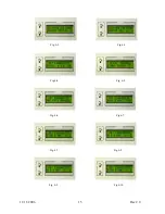
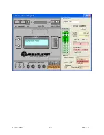
Страница 20: ...11 11 2006 15 Rev 2 0 Fig 6 2 Fig 6 3 Fig 6 4 Fig 6 5 Fig 6 6 Fig 6 7 Fig 6 7 Fig 6 8 Fig 6 9 Fig 6 10...
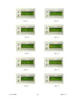
Страница 21: ...11 11 2006 16 Rev 2 0 Fig 6 11 Fig 6 12 Fig 6 13 Fig 6 14 Fig 6 15 Fig 6 16 Fig 6 17 Fig 6 18 Fig 6 19 Fig 6 20...
Страница 28: ...11 11 2006 23 Rev 2 0...
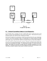
Страница 38: ...Ring B Ring A Fig 12 4 Loop Back Operation PX 2300M LLOOP TxA RxB PX 2300M RLOOP PX 2300M RLOOP BER Tester...
Страница 44: ......

