background image

mcr DOR smoke control dampers 


„MERCOR” S.A. 

– The company reserves the right to modify and change the document.. Version: mcr DOR 22.05.04.1 

7/16 


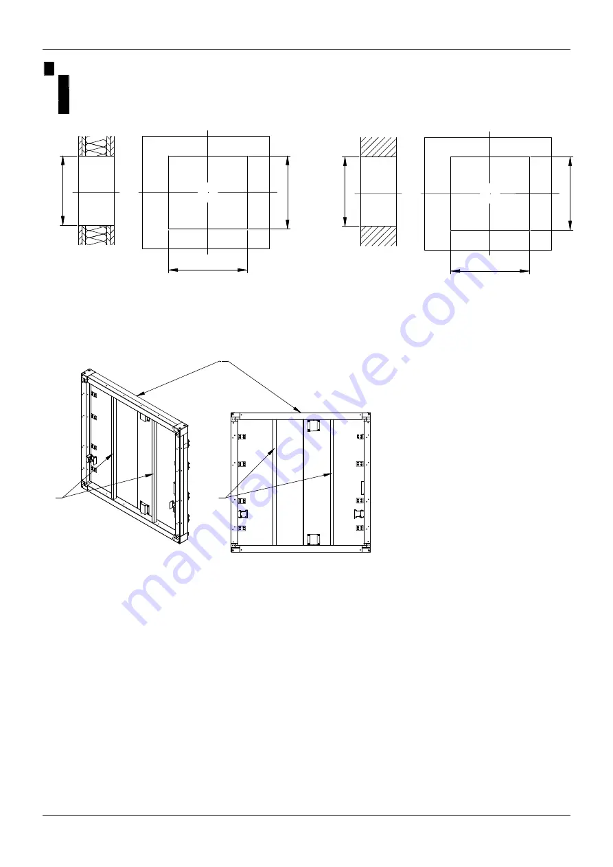
 Installation in the duct in accordance with EN1366-8 and  EN1366-9, passing through the wall:


 fire-proof board thickness 40mm:  

X min. = 85mm 


 fire-proof board thickness 50mm: 

X min. = 105mm 


 fire-proof board thickness 60mm: 

X min. = 125mm 


H

 +

 X

B + X

H

 +

 X

B + X

H

 +

 X

H

 +

 X


Preparation of the installation opening. 


6.3.


EMBEDDING / FIXING THE DAMPER 

2

2

1


1.  Damper mcr DOR BxH 
2.  Wooden blocks  

Protecting the damper against buckling.


The mcr DOR damper will work properly if the partition rotation axis is horizontal. The trigger control 

gear may be located on the right or on the left hand side of the damper at any direction of air flow.  
 

Before embedding/fixing, place the damper axially aligned within the partition in the finished installation 

opening. Level the device and secure in place. The gap between the flap housing, and the wall should be 
thoroughly filled with the appropriate mortar, ensuring fire resistance of the wall and damper, paying special 
attention so that it does not get to the executive elements of  the flap (release and control mechanism, 
partition, seals, limiters). To this end, before assembly, the flap must be strictly protected with foil or other 
protective material until the end of masonry and finishing works. The partition must remain closed until the 
mortar is tied. After binding the mortar, remove the brackets and re-open and close the flap to check the 
correctness  of  its  operation.  In  the  case  of  mounting  the  damper  in  the  wall  of  the  boards,  the  space 
between the damper housing and the wall should be tightly filled with mineral wool, having an A1 non -
reality class confirmed by a certificate, and density and thickness ensuring fire resistance not less than the 
resistance of the wall in which the damper is installed. The filled space should be additionally sealed with 
an appropriate mortar or putty with fire resistance required for the wall. 

Connecting the inserted damper to the ventilation duct must be made in co-coaxial. When installing the 

damper  in  the  partition,  the  damper  body  can  not  be  damaged,  and  in  particular  to  the  formation  of 

Содержание mcr DOR

Страница 1: ...ul Grzegorza z Sanoka 2 80 408 Gdańsk tel 58 341 42 45 tel fax 58 341 39 85 OPERATION AND MAINTENANCE MANUAL OMM Smoke control dampers mcr DOR Version mcr DOR 22 05 04 1 FIRE VENTLIATION SYSTEMS ...

Страница 2: ...SEMBLY INSPECTION 6 6 2 INSTALATION OPENING 6 6 3 EMBEDDING FIXING THE DAMPER 7 6 4 ELECTRICAL CONNECTION 12 7 TRANSPORT STORAGE CONDITIONS 14 8 MAINTENANCE AND SERVICING 14 9 WARRANTY TERMS CONDITIONS 15 Technical Manual designations Option available Option unavailable CAUTION All previous issues of this Technical Manual expire on the date of issue hereof The Technical Manual does not apply to th...

Страница 3: ...systems The dampers cannot be operated in systems exposed to dust except for when they are included in a special individually developed programme of service and technical inspections Fire resistance The damper type mcr DOR has the following fire resistance EI180 ved i o S1500 C300 AA multi depending on the application method and place of installation of the fire damper Execution version The damper...

Страница 4: ...ed before installation in the fixing structure Doing so may damage the drive mechanism and partition and is not covered by the warranty To close the damper partition there are handles located on the partition Before closing the partition unlock it To do this gently pull the movable blocking element until it is moved to the 90 position then start closing the door by holding the handles It is recomm...

Страница 5: ...s 75 Bw B 80 mm 110 Hw H 80 mm 40 40 B H mm H 15 mm B mm H mm B 15 mm A A M 8 mcr DOR damper in closed position B 2 12 B mcr DOR damper in open position 5 DEVICE IDENTIFICATION mcr DOR B x H 1 2 3 All exact trade markings of devices are available in the Technical Catalog Optional fittings Material Trigger control gear Width x height nominal Damper type ...

Страница 6: ...batteries sets The mcr DOR dampers can also be installed in partitions with a lower fire resistance class In the case of such installation the fire dampers have the fire resistance equal to the fire resistance of the partition while maintaining the smoke tightness criterion When installing a damper in a given type of wall the thickness of which is less than required locally e g by installing an ad...

Страница 7: ...ate mortar ensuring fire resistance of the wall and damper paying special attention so that it does not get to the executive elements of the flap release and control mechanism partition seals limiters To this end before assembly the flap must be strictly protected with foil or other protective material until the end of masonry and finishing works The partition must remain closed until the mortar i...

Страница 8: ...the correct operation of the damper again When installing mcr DOR dampers do not expose swelling seals installed in the housing to high temperatures The detachment of the seals prevents the damper from closing After completing the installation clean the damper thoroughly and make sure that the remains of debris did not remain in it that could affect the correct operation of the damper In order to ...

Страница 9: ... length of the BxH side 4 Shaft wall 5 Vertical fire ventilation shaft 6 Wall of a shaft compliant with EN1366 8 or EN1366 9 Damper installation in shafts with a thickness of 110 mm 1 2 3 4 5 1 Damper mcr DOR BxH 2 Masking grille MWD option 3 A strip of fire proof board along the entire length of the BxH side 4 Wall of a shaft compliant with EN1366 8 or EN1366 9 5 Vertical fire ventilation shaft D...

Страница 10: ... wall Installation of protection elements against mechanical damage to the mcr DOR damper 1 4 3 2 5 1 Damper mcr DOR BxH 2 Multi compartment smoke extract duct e g made of fire proof boards 3 A strip of fire proof board along the entire length of the BxH side 4 Cardboard wall 5 Masking grille MWD opiton Damper installation in light walls plasterboard with a multi compartment horizontal ducts ...

Страница 11: ... 4 Installation hangers system 5 M10 x 20 bolt 6 Masking grille MWD opiton Damper installation in a multi compartment horizontal ducts CAUTION Smoke extraction ducts should be made in accordance with the ducts manufacturer s guidelines The ducts must have an adequate fire resistance rating in accordance with the fire resistance rating provided for the entire solution Seal all connections between t...

Страница 12: ...s part of the service after starting the release and control mechanism clean the electromagnets contact surfaces should be cleaned Release and control mechanism EM24xxD EM24D I EM24D P EM230D I EM230D P MP230 24 Rated voltage 24V DC 24V DC 230V AC 230V AC 230V AC Power intake 3 5W 1 6W 4VA 5 5VA 2W Connection Terminal block 10x2 5mm2 Terminal block 10x2 5mm2 Terminal block 4x0 5mm2 Output voltage ...

Страница 13: ... temperature 25 850 C Housing Plastic Power supply Terminal number 1 2 terminal no 1 terminal no 2 Limit switch WK1 damper closed Terminal number 6 5 type NO Terminal number 4 5 type NC Limit switch WK2 damper opened Terminal number 9 8 type NO Terminal number 7 8 type NC Limit switch WK2 damper opened Terminal number 12 11 type NO Terminal number 10 11 type NC Damper closed Transition Damper open...

Страница 14: ...of 20 ºC the ambient temperature is between 20 ºC and 40 ºC there are no vibrations 8 MAINTENANCE AND SERVICING The equipment from Mercor SA requires periodic technical inspection and maintenance at least every 12 months throughout its operating life i e during the warranty and post warranty period Inspection and maintenance may only be carried out by the manufacturer or contractors authorised by ...

Страница 15: ...uyer holder of the guarantee 10 The warranty does not cover Any damage or failure of the equipment caused by improper operation tampering failure to conduct periodic technical inspection and or maintenance established in the Operating and Maintenance Manual section SERVICING AND MAINTENANCE Any damage beyond reasonable control of MERCOR SA and specifically caused by force majeure such as torrentia...

Страница 16: ...s holder modifies the product design without prior authorisation from MERCOR SA Periodic technical inspection and or maintenance is not carried out per schedule and or is carried out by unauthorised personnel or service providers not authorised to do so by MERCOR SA and or the equipment has not been properly operated Unauthorised personnel attempts any intervention in the product outside of the no...

Отзывы: