mcr DOR smoke control dampers
„MERCOR” S.A.
– The company reserves the right to modify and change the document.. Version: mcr DOR 22.05.04.1
12/16
6.4.
ELECTRICAL CONNECTION
With the fire damper properly installed and embedded connect the electrical system wiring to the fire
damper, if the device features controls or other parts that require electric power supply. The following
shows the connection diagrams and basic electrical data for the trigger control gears supplied with the
mcr DOR dampers.
Dampers with a "impulse" type controlling mechanism open as a result of the voltage (current pulse min.
5s twice), as a result of propulsion springs affecting the damper partition. The dampers are closed after
removing the power supply voltage from the mechanism clamps and manually set the dampers partition
to the close position.
Dampers with a "break" type controlling mechanism open open as a result of a break of the voltage, as a
result of propulsion springs affecting the damper partition. The dampers are closed after manually set the
dampers partition to the close position, then supplying the supply voltage.
As part of the service, after starting the release and control mechanism, clean the electromagnets contact
surfaces should be cleaned.
Release and control mechanism EM24xxD
EM24D-I
EM24D-P
EM230D-I
EM230D-P
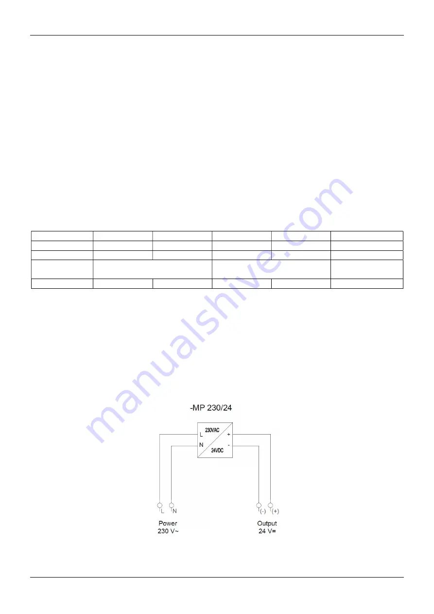
MP230/24
Rated voltage
24V DC
24V DC
230V AC
230V AC
230V AC
Power intake
3,5W
1,6W
4VA
5,5VA
2W
Connection
Terminal block 10x2,5mm
2
Terminal block 10x2,5mm
2
Terminal block
4x0,5mm
2
Output voltage
X
X
X
X
24V DC stabilized
For a triggering and control mechanism of the damper, should be provided with adequate power supply,
guaranteeing the control of the control signal or voltage to the device in the event of a fire. The electrical
connection should be made accurately according to the attached scheme and in accordance with the
instructions presented in point 6.4 of this documentation. It should be made by a person with confirmed
electrical qualifications, in accordance with applicable regulations. All dampers service works should only
be carried out after disconnecting the device from the power supply.
CAUTION
For proper work of the device, it is recommended that the rated voltage housed tolerance of
24V±2% or 230V±2%. Power supply devices other than listed above may cause malfunction and
will not be covered by the warranty conditions.
Connection diagram for transformer module type MP230/24


