background image

20MH70S00 E3 


2019-10-24

Page 4

About this Document   

About this Document

This document is intended only for system developers and integrators.
It describes the design, functions and connection of the product. The manual does not

include detailed information on individual components (data sheets etc.).
It provides an overview of the system and describes possible functions. For a detailed

description of the functionality of the individual boards please refer to the boards’ user

manuals.

History

MH70S product page with up-to-date information and downloads:

www.men.de/products/mh70s/

Issue

Comments

Date

E1

First issue

2015-12-11

E2

Updated according to current BTO excel file, new 

structure

2017-09-15

E3

Added G227 (G212 not supported anymore)

Updated G22 (not supported anymore)

Updated Chapter Cooling Concept

Updated Chapter Safety Instructions for Mounting

Updated Chapter Slots of the MH70S

2019-10-24

Содержание MH70S

Страница 1: ...User Manual MH70S Rugged Data Storage NAS Computer with Intel Core i3 i5 i7 Modular Embedded System for Industrial Automation Railway Transport 2019 10 24 20MH70S00 E3...

Страница 2: ...ing the MH70S 22 2 4 1 Safety Instructions for Mounting 22 2 4 2 Wall Mounting the MH70S 23 2 4 3 Mounting the MH70S in a 19 Rack 25 2 5 Connecting and Starting 29 2 5 1 Safety Instructions for Connec...

Страница 3: ...oard 42 Figures Figure 1 MH70S configuration example maximum configuration 12 Figure 2 Bottom and top of system not covered airflow from bottom to top 16 Figure 3 Product label BTO model 17 Figure 4 P...

Страница 4: ...possible functions For a detailed description of the functionality of the individual boards please refer to the boards user manuals History MH70S product page with up to date information and downloads...

Страница 5: ...t links directly to the Internet When no globe icon is present the hyperlink links to specific information within this document Italics Folder file and function names are printed in italics Comment Co...

Страница 6: ...notices and safety instructions Qualified personnel are those who based on their training and experience are capable of identifying risks and avoiding potential hazards when working with these product...

Страница 7: ...us a so called downstream user in terms of REACH The products MEN supplies are solely non chemical goods Moreover and under normal and reasonably foreseeable circumstances of application the goods sup...

Страница 8: ...e MEN products for any unintended or unauthorized application the customer shall indemnify and hold MEN and its officers employees subsidiaries affiliates and distributors harmless against all claims...

Страница 9: ...ro Elektronik SAS 18 rue Ren Cassin ZA de la Ch telaine 74240 Gaillard Phone 33 450 955 312 info men de www men de info men france fr www men france fr USA MEN Micro Inc 860 Penllyn Blue Bell Pike Blu...

Страница 10: ...e implemented For robust and safe operation the HDD carriers can be configured in RAID 0 1 or 5 while the carriers themselves have their own internal RAID 0 1 and JBOD hardware configuration possibili...

Страница 11: ...recorder or as an NAS system The system can be used with the open source OpenMediaVault operating system The operating system OpenMediaVault is based on the Linux distribution Debian and offers a com...

Страница 12: ...6 Slot PSU CPU I O I O I O I O I O 1 I O STATUS DC DC 120W PU20 CompactPCI Serial EJECT HP AC2 AC1 LOC PWR CompactPCI Serial EJECT HP AC2 AC1 LOC PWR CompactPCI Serial EJECT HP AC2 AC1 LOC PWR Compact...

Страница 13: ...ls fan provides status LEDs and power button Power Supply PSU 3U Configurable yes Possible Configurations 120 W 3U 6 HP PSU wide range input 24 to 110 V DC 24 V DC nom output 12 V 5 V 3 3 V DC 40 C to...

Страница 14: ...ctors at front 0 C to 60 C 4 1000Base T Ethernet interfaces 4 M12 connectors at front 40 C to 85 C conformal coating Ethernet Switch Functionality CPCI Serial 3U Board Configurable yes Possible in Com...

Страница 15: ...formation video distribution systems with PoE and fans Temperature range storage 40 C to 85 C Cooling concept Air cooled forced convection with fan tray at system bottom Relative humidity operation ac...

Страница 16: ...ion Natural convection for fanless operation Not possible with MH70S Forced convection using two fans in a fan tray at the bottom of the housing Required with some of the CPUs available Figure 2 Botto...

Страница 17: ...duct family and model To be complete it must have 9 characters Revision number Indicates the design revision of the product Serial number Unique identification assigned during production Ordering key...

Страница 18: ...r dangerous voltage and can cause fire Damaged equipment has unpredictable behavior and characteristics Prevent damaged equipment from being installed and put into operation Mark the damaged equipment...

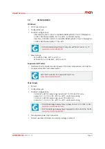
Страница 19: ...system Remove the carrier board from the system If there are already HDDs SSDs installed Installing the first HDD SSD Place the first HDD SSD in the slot close to the front panel on the carrier board...

Страница 20: ...o the front panel with a M3x6 TX8 screw Apply thread locker to ensure the screws are not loosened by vibrations Installing the second HDD SSD Place the second HDD SSD in the slot close to the rear con...

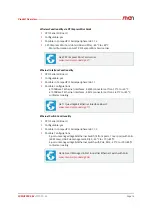
Страница 21: ...the bottom side with two M3x8 TX8 socket head screws position highlighted in red in the following drawing Secure the HDD SSD additionally by fixing it to the guide rail with a M3x6 TX8 screw Apply thr...

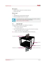
Страница 22: ...s specified in the Technical Data Leave enough space to the sides of the system that are needed for cooling to enable the required airflow as specified in chapter Cooling Concept Do not cover openings...

Страница 23: ...ounting brackets have to be moved to the rear of the system The following steps are necessary To remove the mounting bracket loosen the two screws securing the mounting bracket After removing the moun...

Страница 24: ...t with the M4x12 TX20 countersink head screws included in the delivery Repeat the above process for the mounting bracket on the other side of the system Apply thread locker to all mounting screws to e...

Страница 25: ...racket at the right side of one MH70S and on the left side of the other MH70S Place the front and rear bonding brackets supplied with the bonding kit as shown in the following illustration Secure the...

Страница 26: ...wo MH70S systems next to each other and slide them together so that the screw holes in the bonding kit brackets are aligned as in the following picture Moun ng screw Moun ng screw Side Panel Front pan...

Страница 27: ...Getting Started 20MH70S00 E3 2019 10 24 Page 27 Connect the systems using four M3x8 countersink head screws two screws at the front and two at the back Bonding kit brackets M3x8 countersink head screw...

Страница 28: ...the system The following steps are necessary Remove the mounting bracket at the right side of the MH70S Screw the kit to the right side of the MH70S using four M4x12 screws Apply thread locker to all...

Страница 29: ...to identify risks and avoid potential hazards when working with these products systems Any power input must be protected by an external fuse as defined in chapter Connecting the Power Supply Implemen...

Страница 30: ...onfiguration and coding labeling on the system for the exact config uration and pin assignment Figure 4 Power configuration and coding labeling example Plug an external power supply to the power inlet...

Страница 31: ...cription on how to install driver software please refer to the respective documentation of the software package to be installed See Chapter 3 1 1 Power Button on page 32 See the MEN website for the CP...

Страница 32: ...ICON plug e g Phoenix Contact IC 2 5 3 STGF 5 08 Mating 3 pin COMBICON receptacle e g Phoenix Contact FKCT 2 5 3 STF 5 08 1 Vin 2 PE 3 Vin Signal Direction Function PE Shield Vin Ground Vin in Power i...

Страница 33: ...ow In normal operation you do not have to make any changes in the configuration 3 2 1 Control Panel LEDs The status of the MH70S is signalled using LEDs at the front of the system The following table...

Страница 34: ...SU detects a problem in the system power supply Off all other states Fan Fail Red On fan failure is detected Off all other states Temp Fail Red Blinking system temperature too cold On system temperatu...

Страница 35: ...C DC 120W PU20 2 3 4 5 6 Slot PSU CPU I O I O I O I O I O 1 I O STATUS DC DC 120W PU20 CompactPCI Serial EJECT HP AC2 AC1 LOC PWR CompactPCI Serial EJECT HP AC2 AC1 LOC PWR CompactPCI Serial EJECT HP...

Страница 36: ...eral I O 1 G304 Smart Managed 4 Port Industrial Ethernet Switch with PoE G211 Quad Gigabit Ethernet Interface Board G212 Wireless Network Board for 2 PCIe and 2 SIM Cards2 G227 Wireless Network Board...

Страница 37: ...sted Platform Module TPM A trusted platform module for authenticating the hardware to ensure platform integrity is available on the MH70S The TPM module is compliant to the TPM v1 2 specification Proc...

Страница 38: ...10 HDDs installed 5 transparent for CPU RAID levels 0 1 and 5 with hot spare disc on system level depends on operating system support RAID levels 0 1 and JBOD on one G503 carrier Hot swap support Auto...

Страница 39: ...o the PCI Express Mini Card Standard 4 Reverse SMA Antenna connectors 2 micro SIM card holders To get access to a mobile phone network you need a SIM card subscriber identity module and a contract wit...

Страница 40: ...ystem and the labels are not damaged The MH70S is equipped with a lithium battery There is a danger of explosion if the battery is incorrectly replaced Replace only with the same or equivalent type Ma...

Страница 41: ...lowing components use fuses PU20 3U 6 HP PSU Wide Range Power Supply Unit for Railway Systems 24 to 110 VDC 120 W www men de products pu20 PU21 3U 6 HP PSU Wide Range Power Supply Unit for Railway Sys...

Страница 42: ...el is smoothly aligned to the neighboring front panels If the board has an ejector Turn the ejector up until it clicks into place Fasten the fixing screws tightening torque 0 3 Nm 4 4 2 Removing a Plu...

Страница 43: ...gn the handle with the fixing screws turn the handle so it aligns with the front panel then pull the assembly out of the slot If you do not have a board removal handle Firmly grip both fixing screws o...

Отзывы: