9
Refer to page 5 for item part numbers,
descriptions and quantities
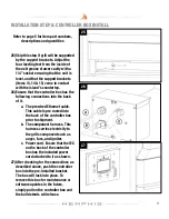
25)
Skip this step if grill will be supported
by the support brackets. Adjust the
four leveling feet from the inside of
the ash/grease drawer cavity with a
1/4” socket ensuring that the unit is
level, and that the support brackets
(items 13,14 & 15) come in contact
with the island’s countertop.
26)
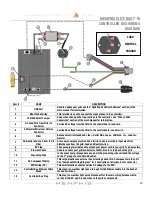
Ensure that the controller box has the
following connections into the back
of it.
a.
The prewired Ethernet cable.
This cable is pre routed into
the back of the controller box
prior to shipment.
b.
The component harness. This
harness carries electricity to
the grills component such as
auger, fans, and igniter.
c.
Power cord. Ensure that the IEC
on the back of the controller
box has the included power
cord attached to it as shown.
27)
After checking for the connections as
described above, push the controller
box into the pre-installed bracket.
The box will lock into place. To
remove this box for maintenance or
software updates in the future,
simply pull on the controller box and
the ball detents will release.
INSTALLATION STEP 5: CONTROLLER BOX INSTALL
25
26
27


