Chassis Installation
Rev A04
Mellanox Technologies
46
the depth of the rack. This way, the chassis can be mounted evenly with the rear or the front of the
rack facilitating access to the 10GbE connectors and power connections.
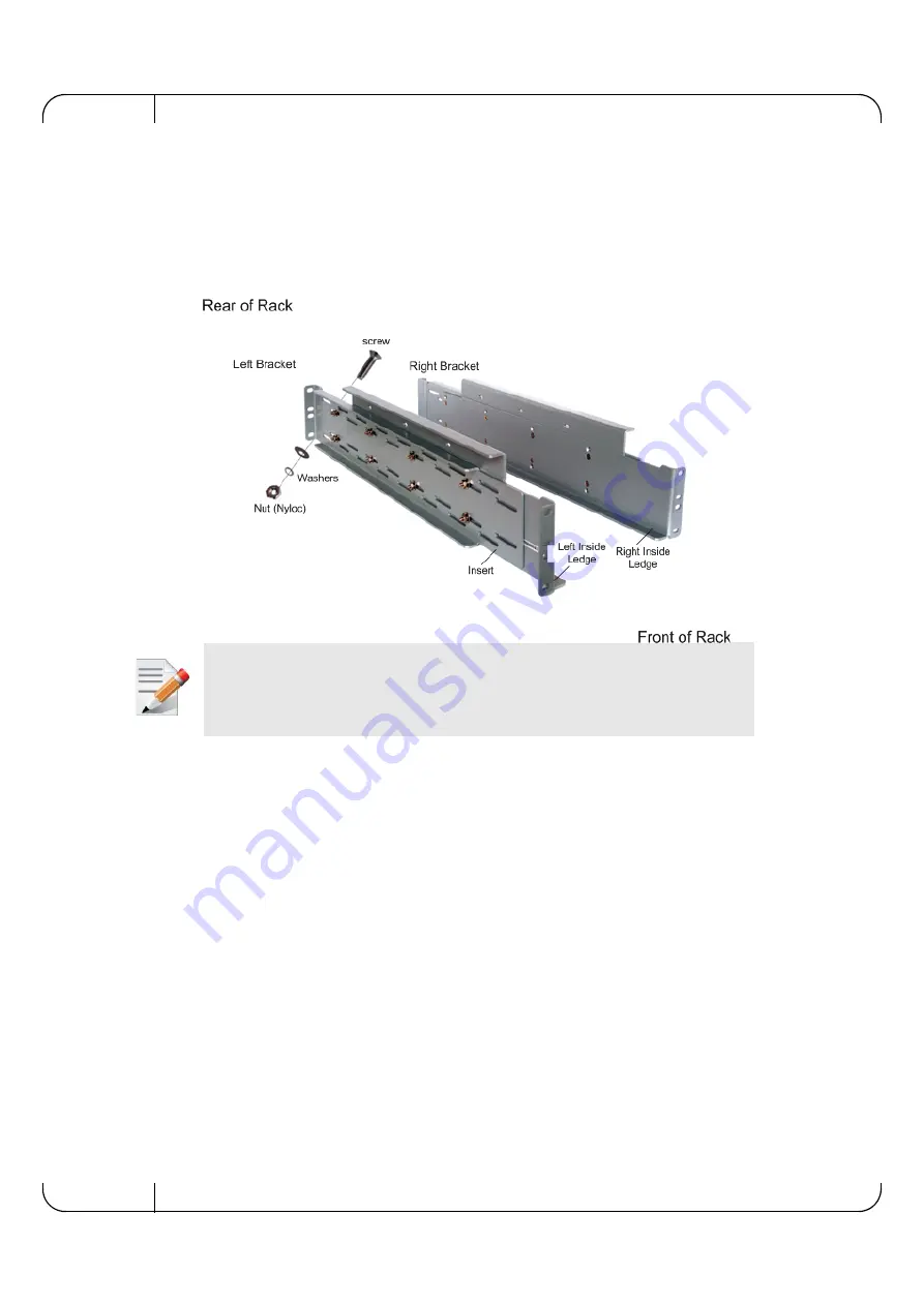
The following illustrates two assembled brackets (left and right), and shows the interior side of the
left bracket when it is attached to the rack.
Figure 20: Rail Kit Components - Left Bracket, Right Bracket, Screws, Washers and Nuts
4.1.1.2 Rail Kit Assembly Procedure Summary
To assemble the rail kit (both rails):
1. Use 8-32 5/8" screws and flat washers and spring provided with the kit to assemble each rail. Position
the insert in front of the bracket for each rail.
2. For each rail, take a bracket and attach an insert (the two inserts are identical). At this stage,
position the two parts to fit the distance between the rack rails of each side.
Ensure that:
•
You are using the right bracket for the right rail (right side when facing the front of the
rack) and the left bracket for the left rail (left side when facing the front of the rack).
•
The insert is identical for both rails.
•
The rail supports six or eight 8-32 5/8" screws; eight are recommended.
When assembling and mounting the rail, the required torque force is 10 lb. in (using a drill-like
electric screwdriver).
3. Choose the threaded holes in the bracket.
•
Use all 8 screws; note the order of the nuts and washers.
•
User all the inner opening sets (as shown in the photo) or other openings, depending
on the rack vertical rail locations.


