


- 18 -
C-VX875
Instructions Manual
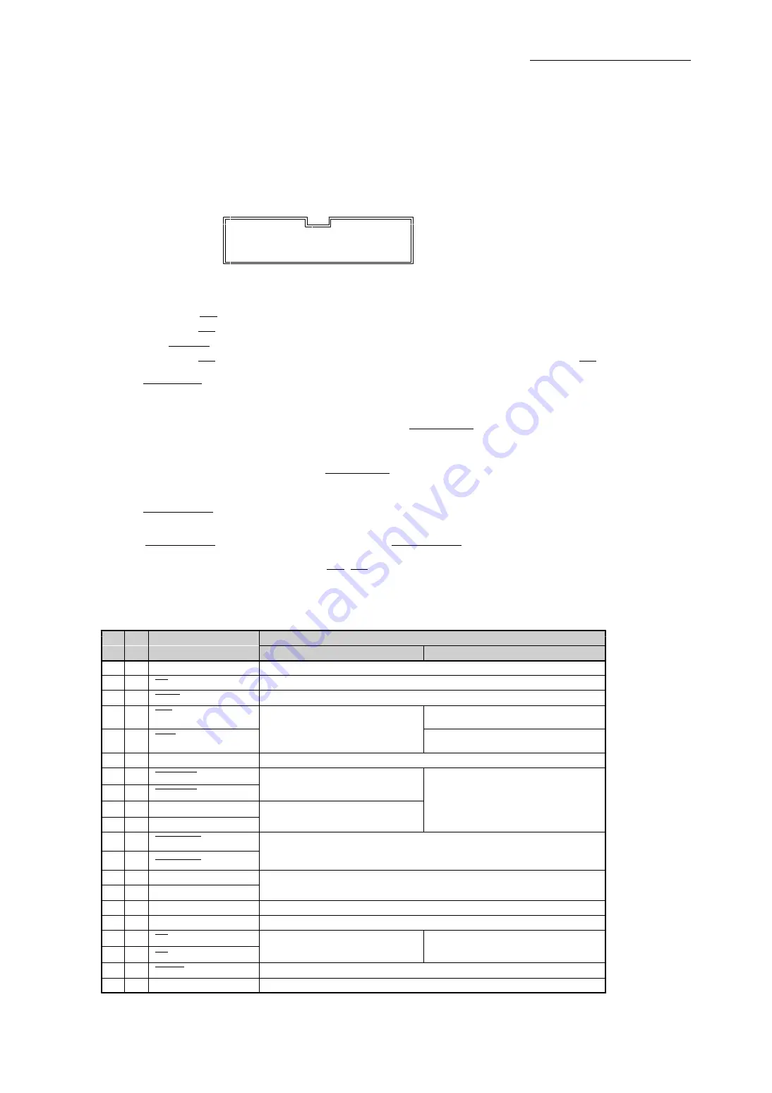
(3) Special‑purpose I/O connector (J3)
The conector of the applied function.
■Pin assignment
・Connector type name
:XG4C‑2031 (OMRON)
・Adaptable connector socket
:XG4M‑2030 (OMRON, Not accessories.)
・Adaptable cable
:CE‑13
(MIL 20P 1.5 m flat cable. Not accessories.)
19
1
■ ■ ■ ■ ■ ■ ■ ■ ■ ■
■ ■ ■ ■ ■ ■ ■ ■ ■ ■
20
2
■Signal table
・All input signal is not able to set time constants, to switch logic.
(Note 1) When the MAN signal goes low, this bord is MANUAL mode.
When the MAN signal goes high, this bord return to BUS mode.
The MAN RDY signal is enable to go high by MAN MASK command.
When the MAN signal is low level, this bord is not MANUAL mode by setting MAN signal low level.
(Note 2) SIGNAL INx input signal can be use general‑purpose sensor function and synchronous start
function. If these signal is used, set the functions that need to be changed from their values.
The initial value after the relevant signal is reset is "No function" .
If this bord is MANUAL mode, You can not use SIGNAL INnx input signal.
When this bord is MANUAL mode, this signal(SEL A‑D) enable to select an axis that perfoms
MANUAL SCAN drive.
The functions assigned to the SIGNAL INnx
input signal are invalid. And when this bord
returns to BUS mode, the functions assigned to this signal are valid.
(Note 3) SIGNAL OUTnx output signal can be output status signals of any axes by setting status output
function. The initial values after the relevant signal is reset are as follows:
SIGNAL OUTn0 is CNTINT signal of Xn axis. SIGNAL OUTn1 is CNTINT signal of Yn axis.
(Note 4) When this bord is MANUAL mode, SS0,SS1 input signal(SEL A‑D) enables general‑purpose sensor
that MANUAL SCAN drive specified axis.
When general‑purpose sensor function is set as "UP/DOWN/CONST command", this input signal
enable acceleration/deceleration command signal of MANUAL SCAN drive.
Pin
Dir
Signal name
Description
No
BUS mode
MANUAL mode
1
−
D.GND
GND(in5V GND)
2
In
MAN
MANUAL mode select signal
(Note 1)
3
In
FSSTOP
All axes immediate stop signal
4
In
CWMS
CW direction MANUAL SCAN
drive command signal
Invalid
5
In
CCWMS
CCW direction MANUAL SCAN
drive command signal
6
−
D.GND
GND(in5V GND)
7
In
SIGNAL IN0 / SEL A
General‑purpose,
synchronous start signal
(Note 2)
8
In
SIGNAL IN1 / SEL B
The signals can be combined to
select the axis used for manual
9
In
SEL C
operation.
Invalid
10
In
SEL D
11
Out
SIGNAL OUT0
(The initial value after resetting:XCNTINT)
Staus output signal
(Note 3)
12
Out
SIGNAL OUT1
(The initial value after resetting:YCNTINT)
13
Out
NC
Reserved
14
Out
NC
15
−
D.GND
GND(in5V GND)
16
Out
+5V
In5V
17
In
SS0
MANUAL SCAN drive acceleration/
Invalid
deceleration command signal
18
In
SS1
(General‑purpse sensor signal)
(Note 4)
19
Out
MAN RDY
Permission signal switching MANUAL mode
(Note 1)
20
−
D.GND
GND(in5V GND)