MeiTrack iButton T1 Скачать руководство пользователя страница 9

MEITRACK T1 User Guide                                                    


Copyright © 2018 Meitrack Group All rights reserved.                                                - 9 - 

Blink (every 0.1 seconds) 

The device is being initialized or the battery power is low. 

Blink (0.1 seconds on and 2.9 seconds off) 

A GPS signal is received. 

Blink (1 second on and 2 seconds off) 

No GPS signal is received. 

GSM Indicator (Green)


Steady on 

A call is coming in or a call is being made. 

Blink (every 0.1 seconds) 

The device is being initialized. 

Blink (0.1 seconds on and 2.9 seconds off) 

A base station signal is received. 

Blink (1 second on and 2 seconds off) 

No base station signal is received. 


6.4


Configuring Device Parameters by Meitrack Manager 

This section describes how to use Meitrack Manager to configure the device on a computer. 
Procedure: 
1.


Install the USB driver and Meitrack Manager. 

2.


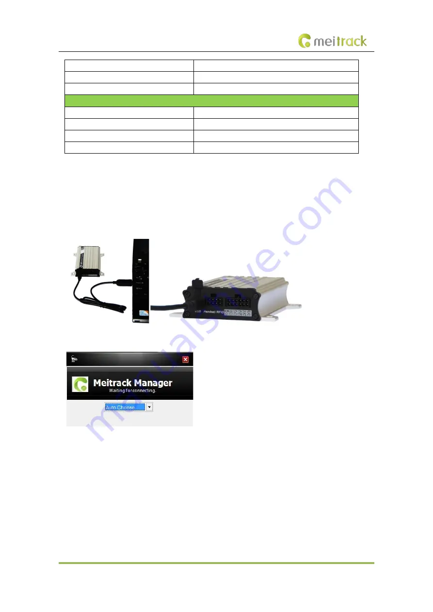
Connect the device to a computer by using the USB cable. 


3.


Run Meitrack Manager, then the following dialog box will appear. 


4.


Turn on the device, then Meitrack Manager will detect the device model automatically and the parameter 
page will appear accordingly. 

For details about Meitrack Manager, see the 

MEITRACK Manager User Guide

6.5


Tracking by Mobile Phone 

Call or send the 

0000,A00

 command by SMS to the device's SIM card number. The device will reply to an SMS with 

a map link. 
Click the SMS link. The device's location will be displayed on Google Maps on your mobile phone. 
Note: Ensure that  the  device's  SIM  card number  has  subscribed  the caller ID service. Otherwise, the tracking 
function by mobile phone will be unavailable. 

Содержание iButton T1

Страница 1: ...MEITRACK T1 User Guide MEITRACK T1 User Guide...

Страница 2: ...018 Meitrack Group All rights reserved 2 Change History File Name MEITRACK T1 User Guide Project T1 Creation Date Update Date 2014 06 10 2018 08 02 Subproject User Guide Total Pages 18 Version V2 8 Co...

Страница 3: ...evice 8 6 3 LED Indicator 8 6 4 Configuring Device Parameters by Meitrack Manager 9 6 5 Tracking by Mobile Phone 9 6 6 Common SMS Commands 11 6 6 1 Setting Authorized Phone Numbers A71 11 6 6 2 Settin...

Страница 4: ...You can detect the harsh acceleration braking alert by setting the limit value Cautions on device installation 1 The device should be installed into the vehicle according to the following direction 2...

Страница 5: ...uel power cut off Engine or vehicle door status alert Towing alert Polygonal geo fence alert Fuel stolen alert 3 1 3 Monitoring Harsh braking and Harsh acceleration Idle Recovery Fatigue Driving Speed...

Страница 6: ...rt the vehicle Monitor driver attendance by RFID report LED display Display advertisements and announcements Tire pressure sensor Monitor tire pressure and temperature in real time Ultrasonic fuel lev...

Страница 7: ...to connect a digital temperature sensor or iButton 4 T1 and Accessories T1 and standard accessories T1 with a built in battery External GSM antenna I O cable SOS button External GPS antenna USB cable...

Страница 8: ...lance Ensure that the phone card PIN lock has been closed properly Ensure that the SIM card in the device has subscribed the caller ID service if you want to use your authorized phone number to call t...

Страница 9: ...w to use Meitrack Manager to configure the device on a computer Procedure 1 Install the USB driver and Meitrack Manager 2 Connect the device to a computer by using the USB cable 3 Run Meitrack Manager...

Страница 10: ...current location or the alert type 061314 10 36 Indicates the date and time in MMDDYY hh mm format None V The GPS is invalid A Valid V Invalid 26 Indicates the GSM signal strength Value 1 32 The large...

Страница 11: ...n sequence The tracker will stop dialing when a phone number responds Example Sending 0000 A71 13811111111 13822222222 13833333333 Reply 353358017784062 A71 OK 6 6 2 Setting Listen in Phone Numbers A7...

Страница 12: ...OK 6 6 4 Selecting a Serial Port and Peripheral C70 SMS sending 0000 C70 Serial port selection Peripheral selection SMS reply IMEI C70 OK Description Serial port selection 1 The peripheral port of the...

Страница 13: ...ennas GSM antenna GPS antenna Connect the GSM antenna to the connector which is labeled GSM The GSM antenna is non directional so you can hide it in any place of a vehicle Connect the GPS antenna to t...

Страница 14: ...to an external sensor such as the fuel level sensor 9 Fuel level sensor input Blue and brown Analog input 2 with 12 bit resolution and valid voltage 0 6 6 V The AD cable is equipped with a white plug...

Страница 15: ...ut 3 is connected to the ACC position after the engine is started the platform will read it as ON OFF ON If input 3 is connected to the Start position after the engine is started the platform will rea...

Страница 16: ...rmula is as follows Voltage AD x 3 3 x 2 4096 Pin 9 is connected to the A53 fuel level sensor by default You can install the sensor without calculation formula added on the platform For details see th...

Страница 17: ...peaker Note The RS232 port can be used with either the RFID reader or the camera at a time 8 4 Installing the RFID Reader RS232 Port Pin Number Color Description 1 Red Power output Output voltage 5 V...

Страница 18: ...to the camera To connect T1 to a camera a 4 pin to 8 pin cable is required Connect the device to the 8 pin interface Connect the camera to the 4 pin interface Note The RS232 port can be used with eith...

Отзывы: