Page 8
L2
L1
L3
G
N
D
3.6 Main Electrical Supply Connection
WARNING!
Check that the circuit breaker/fused
disconnect is in the OFF position and
that the unit is switched off before
making the electrical utility connec-
tions.
IMPORTANT
In some cases, local codes dictate that
electrical supply connections be made only
by a certified professional.
1. Check that the incoming power leads are
of sufficient rating for the appliance’s
current draw. Amperage and minimum
supply wire specifications are shown on
the serial plate and on the electrical infor-
mation label inside the control box.
2. Remove the cover panel from the
electrical control box by removing the four
screws that hold it in place.
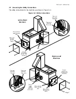
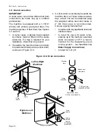
3. Locate the strain relief for the electrical
supply wiring on the back of the control
box (Figure 3-3). Thread the incoming
supply leads through the strain relief and
to the main electrical supply terminal block.
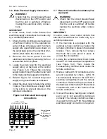
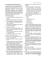
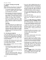
4. Refer to Figure 3-4. Connect the power
supply and ground leads as indicated.
5. Adjust the strain relief to fasten the wiring
in place. You should leave enough slack
in the wiring to prevent stress on the
terminal connections.
S
ECTION
3 - I
NSTALLATION
Figure 3-4: Main electrical supply
connections
GND = ground
L1, L2 and L3 = “hot” (line)
Internal chassis
ground.
Do not connect
supply ground to
this terminal
block.
3.7 Remote Control Box Installation (if so
equipped)
WARNING!
Check that the circuit breaker/fused
disconnect is in the OFF position and
that the unit is switched off before
making the electrical utility connec-
tions.
IMPORTANT
In some cases, local codes dictate that
electrical connections be made only by a
certified professional.
1. If the machine is equipped with the
optional remote control box, fasten the
remote control box in place in the desired
location. Then, remove the four screws
that hold the cover panel in place to
access the connections.
2. Locate the remote terminal block inside
the AZP 80 main electrical compartment
(see Figure 3-4). Then, locate the
corresponding terminal block inside the
remote control box.
3. Route a cable with 10 conductors and a
ground (supplied by others - AWG 16
recommended) between the AZP 80’s
electrical compartment and the remote
control box. Strain reliefs are provided in
the back wall of the main AZP 80 electrical
compartment, and on the bottom of the
remote control box.
4. Connect the cable, making sure to match
each set of corresponding terminals
correctly. The remote control box draws
its power from the AZP 80. No additional
electrical supply connection is required.


