MeiG
Product
Manual
of
SLM750
Module
SLM750
Module
Hardware
Design
Page 48, total 84 pages
Table 14: Pin description for PCM interface
Pin name
Pin
number
I/O
Description
Note
PCM_CLK
27
IO
PCM
clock
1.8V power supply
domain
PCM_OUT
25
DO
PCM data output
1.8V
power
supply
domain
PCM_IN
24
DI
PCM data input
1.8V
power
supply
domain
PCM_SYNC 26
IO
PCM
data
synchronous signal
1.8V power supply
domain
I2C_SCL 41 OD
I2C
clock
Require 1.8V external
pulling-up
I2C_SDA 42 OD I2C
data
Require 1.8V external
pulling-up
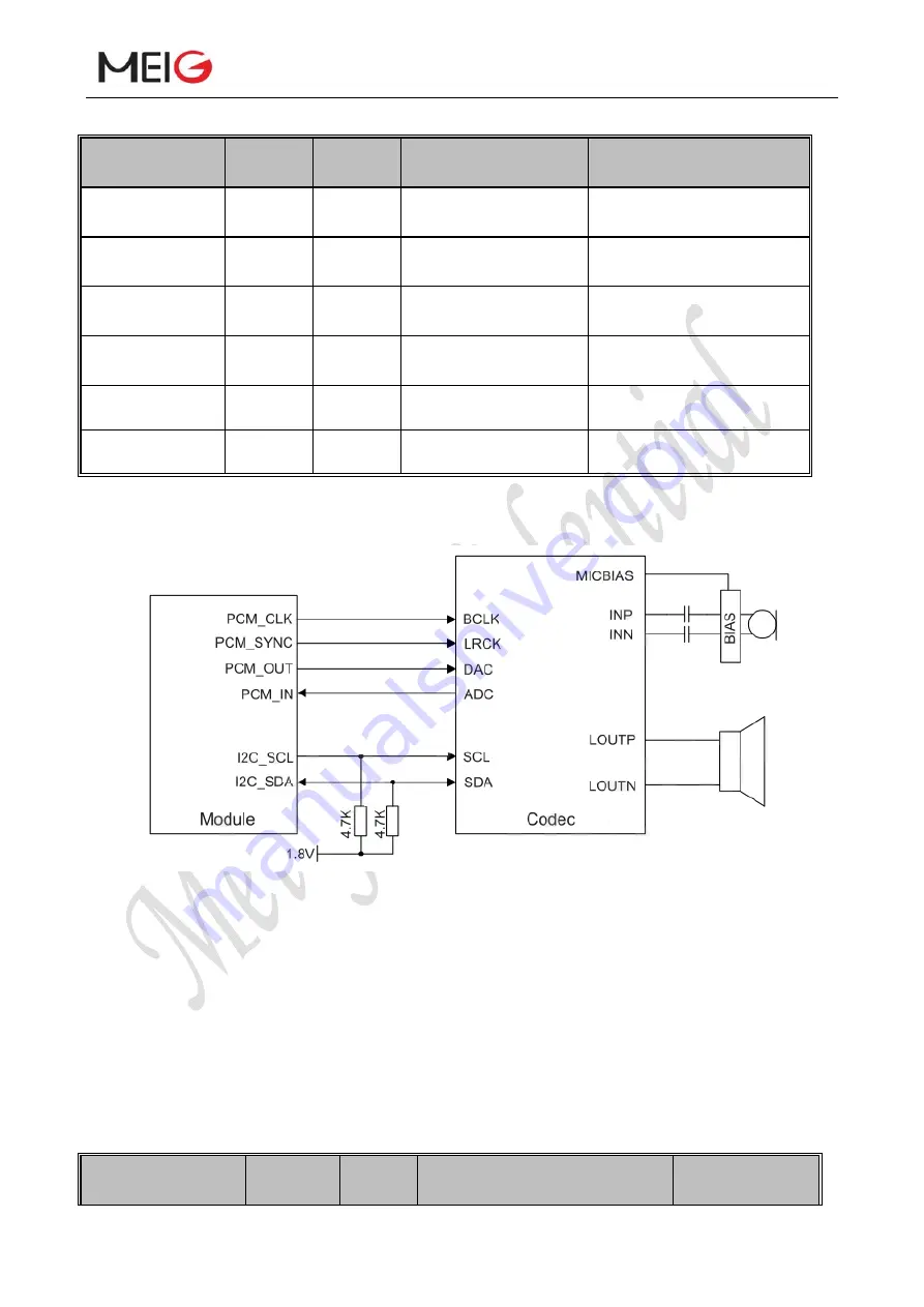
The following figure shows a reference design of PCM interface with an external codec IC.
Figure 20 Reference design for PCM circuit
3.13 Network Status Indication
The network indication pins can be used to drive a network status indicator LED. SLM750
provides two network indication pins: NET_MODE and NET_STATUS. The following tables
describe pin definition and logic level changes in different network status.
Table 15: Pin Definition of Network Indicator
Pin name
Pin
number
I/O
Description
Note


