background image

20 


motor 

model 

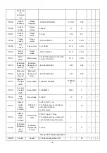
P03.03 

Rated 

current of 

motor  

Rated 

current 

0.1~999.9A 0.1A 

Dependin

g on 

model 

× 

P03.04 

Rated 

frequency 

of motor   

Rated 

frequency 

1.00~3000.0Hz 0.01Hz 

Dependin

g on 

model 

× 

P03.05 

Rated 

rotating 

speed of 

motor  

Rated 

rotating 

speed 

0~60000rpm 1rpm 

1440rpm 

× 

P03.06 

Power 

factor of 

motor  

Power factor

0.001~1.000 

It shall be used when calculating 
the motor parameters with the 
nameplates 

0.001 

Dependin

g on 

model 

× 

P03.07 

Stator 

resistance 

of motor   

Stator 

resistance 

R1 

0.000~65.000 0.001 

Dependin

g on 

model 

× 

P03.08 

Leakage 

inductanc

e of motor 

Leakage 

inductance X

0.0~2000.0 0.1 

Dependin

g on 

model 

× 

P03.09 

Rotator 

resistance 

of motor 

Rotator 

resistance of 

motor 

0.000~65.000 0.001 

Dependin

g on 

model 

× 

P03.10 

Mutual 

inductanc

e of motor 

Mutual 

inductance of 

motor 

0.0~2000.0 0.1 

Dependin

g on 

model 

× 

P03.11 

No-load 

current (I

0

of motor   

No-load 

current (I

0

0.1~999.9A 0.1A 

Dependin

g on 

model 

× 

P03.12 

Overload 

protection 

factor of 

motor 

Overload 

protection 

factor of 

motor 

20.0%~110.0% 
 

0.1% 100.0% 

× 

P03.25 

Paramete

auto-tunin

Parameter 

auto-tuning 

0: Disabled 

1: Enabled (motor in static status)

2: Enabled (motor in rotate status)

1 0 

× 

Group P04: Encoder parameters


P04.01 

Number of 
pulses per 

revolution 

of local 

PG 

Number of 
pulses per 

revolution of 

PG 

1~10000 1 

1024 


P04.02 

Rotation 
direction 

of local 

PG 

PG rotation 

direction 

0: A before B 

1: B before A 

1 0 

 × 

Содержание MV600L Series

Страница 1: ...omer service centers or directly contact Megmeet headquarters Shenzhen Megmeet Drive Technology Co Ltd All rights reserved The contents in this document are subject to change without notice Shenzhen M...

Страница 2: ...institutions MV600L selects these transmission station through a function code and it will bring change of control logic and related function code defaults so as to be convenient for the user MV600L s...

Страница 3: ...ers Group P08 44 4 5 Auxiliary function parameters Group P11 45 4 6 Multi stage reference and simple PLC parameters Group P13 46 4 7 Slewing control parameters Group P13 47 4 8 Lifting control paramet...

Страница 4: ...utput power 400kW kW 2 2 1 2 Product series Table 1 1 Name and model of drive Enclosure model Product model Rated capacity kVA HD Rated input current A Rated output current A Rated output power kW R2...

Страница 5: ...th PG Speed control precision 0 2 vector control without PG 0 02 vector control with PG Speed fluctuation 0 3 vector control without PG 0 1 vector control with PG Torque response 5ms vector control wi...

Страница 6: ...te Indoor away from direct sunlight free from dust corrosive gas combustible gas oil mist water vapor water dripping or salt Altitude Used at the place lower than 1000m derated at the place above 1000...

Страница 7: ...155 198 5 5 4 MV600L 4T7 5 R4 MV600L 4T11 186 314 5 330 209 206 6 5 9 MV600L 4T15 MV600L 4T18 5 R5 MV600L 4T22 220 437 5 451 5 284 5 213 6 5 19 MV600L 4T30 MV600L 4T37 R6 MV600L 4T45 270 549 570 335 2...

Страница 8: ...pe 4 Applicable models MV600L 4T55 MV600L 4T75 R L1 S L2 T L3 TOP DC W T3 P B1 B2 DC U T1 V T2 BOTTOM Terminal terminal type 1 4 Function R L1 S L2 T L3 Three phase AC 380V input terminals DC P B 1 Re...

Страница 9: ...er bus upon delivery P N Reserved for external braking unit DC DC negative bus output terminals U T1 V T2 W T3 Three phase AC output terminals 2 1 1 Drive connection Table 2 1 Recommended fuse capacit...

Страница 10: ...50 2 150 2 1 MV600L 4T280 800 185 2 185 2 1 MV600L 4T315 800 150 2 150 2 1 MV600L 4T355 800 150 2 150 2 1 MV600L 4T400 1000 150 2 150 2 1 Note The parameters listed in this table are recommended value...

Страница 11: ...ion input 3 Multi function input 4 Multi function input 5 Multi function input 6 Multi function input 7 Multi function input 8 Analog input Analog differential input Standard RS485 commmunication port...

Страница 12: ...0 Input current range 0mA 20mA input resistance 246 resolution 1 2000 AI2 Analog single end input AI2 AI3 Analog voltage differential input AI3 or analog voltage single end input For the analog voltag...

Страница 13: ...control and three wire control functions P09 08 in Digital input output parameters Group P09 common terminal PLC Opto isolated input please refer to the introduction to the multifunctional input outp...

Страница 14: ...Multi functional input terminal Short circuited with P24 upon delivery Common terminal of X1 X8 PLC is interally isolated with P24 COM 24V power common terminal 2 common terminals in total used toget...

Страница 15: ...is as shown in Fig 2 4 Fig 2 4 Schematic diagram for wiring of PG with open collector signal 2 When the PG output signal is push pull signal the wiring with the interface board terminal is as shown i...

Страница 16: ...16 Fig 2 6 Schematic diagram for wiring of PG with differential signal MV600L A VCC 0V 12C PE COM A A B B B Shield cable The same as A 3 3V A A B B Shield single end grounded near drive...

Страница 17: ...1 Only P02 05 and this function code can be changed 2 Only this function code can be changed 1 0 P00 05 Paramete r initializatio n Parameter initialization 0 Parameter changing status 1 Clear fault me...

Страница 18: ...00Hz 0 01 0 00 P01 13 Measured frequency of motor Measured frequency of motor 650 00 650 00Hz 0 01 0 00 P01 14 High level of output kWh Output kWh 0 65535 10000kWh 10000kW h 0 P01 15 Low level of outp...

Страница 19: ...requency setting P02 17 P02 16 0 01Hz 8 00 P02 13 Accelerati on time 1 Acceleration time 1 0 0 3600 0 Unit adopts that of P11 01 0 1 Determine d by the operating mode and motor power P02 14 Decelerati...

Страница 20: ...2000 0 0 1 Dependin g on model P03 09 Rotator resistance of motor Rotator resistance of motor 0 000 65 000 0 001 Dependin g on model P03 10 Mutual inductanc e of motor Mutual inductance of motor 0 0 2...

Страница 21: ...000 10 000S 0 001s 0 200s P05 03 Switching frequency Switching frequency 0 0 50 0 0 1 10 0 P05 04 Speed loop high spee d proportion al gain Speed loop high speed proportional gain 0 1 200 0 0 1 12 0...

Страница 22: ...1s 0 5 Group P06 Torque control parameters See the full manual Group P07 VF control parameters P07 00 V F curve setting V F curve setting 0 User customized V F curve 3 High starting torque luffing def...

Страница 23: ...00 10 00s 0 01s 0 10s P08 09 Stop speed detection mode Stop speed detection mode 0 Speed set value the only one detection mode under the V F mode 1 Speed detection value 1 1 P08 10 Stop dwell frequen...

Страница 24: ...erati on time for emergenc y stop Deceleration time for emergency stop 0 00 100 00s 0 Automatic high speed deceleration 0 01s 0 00s Group P09 Digital input output parameters P09 00 P09 07 Function sel...

Страница 25: ...it switch normally closed input P09 14 Input terminal enabled status setting Input terminal enabled status Binary setting 0 Normal logical enabled upon connection 1 Inverted logical enabled upon disco...

Страница 26: ...0 BIT3 Y1 Y2 TATBTC BRABRC 1 0 P09 22 Relay TATBTC BRABRC output delay Relay TATBTC BRABRC output delay 0 1 10 0s 0 1s 0 1 P09 23 Frequenc y arrival FAR detection width Frequency arrival detection wid...

Страница 27: ...nput properties Unit place AI1 0 Voltage input 1 Current input Tens place AI2 0 Voltage input 1 Current input AI3 is the differential voltage input 1 00 P10 01 Analog AI function selection AI function...

Страница 28: ...1 01 0 1 6 00 P11 03 Decelerati on time 2 Deceleration time 2 0 0 3600 0 Unit adopts that of P11 01 0 1 6 00 P11 14 Switching frequency of accelerati on decelerati on time 1 and 2 Switching frequency...

Страница 29: ...0Hz 0 01Hz 0 00 P11 24 Lower limit of skip frequency 3 Skip frequency 3 0 00 P11 23 0 01Hz 0 00 Group P12 Advanced function parameters P12 02 Carrier wave frequency Carrier wave frequency 0 7 15 0kHz...

Страница 30: ...meter s 2 Control optimization parameters 2 0 65536 1 0 Group P13 Multi stage reference and simple PLC parameters P13 00 Multi stag e reference properties setting Multi stage reference properties 0 Mu...

Страница 31: ...ulti stag e reference 10 Multi stage reference 10 0 1 40 0 P13 11 Multi stag e reference 11 Multi stage reference 11 0 1 60 0 P13 12 Multi stag e reference 12 Multi stage reference 12 0 1 80 0 P13 13...

Страница 32: ...65535 hours 1hour 0 Group P25 Slewing control parameters P25 02 Y1 vortex control signal valid Y1 vortex control selection 0 Valid 1 Invalid 1 0 P25 03 Vortex control coefficient Vortex percentage 0 0...

Страница 33: ...1 0 P26 09 The shortest brake delay of closed loop lifting cross The shortest brake delay of closed loop lifting cross 0 0 10 00s 0 01 0 10 Group P60 Brake control parameters P60 00 Forward torque low...

Страница 34: ...it of forward frequency for brake release Lower limit of forward frequency for brake release 0 00 P60 17 0 01Hz 0 85Hz P60 12 Reverse switching frequency for brake release Reverse switching frequency...

Страница 35: ...action selection 0 2 1 1 P61 07 Overspee d threshold Overspeed threshold 80 0 200 0 0 1 120 P61 08 Overspee d detection time Overspeed detection time 0 00 10 00s If set to zero not detected 0 01s 0 00...

Страница 36: ...e to rated current of the drive Er oL2 1 0001 P97 04 Overload pre alarm detection level Overload detection level 20 0 200 0 0 1 130 0 P97 05 Overload pre alarm detection time Overload detection time 0...

Страница 37: ...e deceleration Er oC2 3 Over current when the drive is running with constant speed Er oC3 4 Over voltage during the drive acceleration Er oU1 5 Over voltage during the drive deceleration Er oU2 6 Over...

Страница 38: ...cuit Er GdF 34 Large DEV deviation fault Er dEv 35 Load loss fault Er oFL 36 Brake loosened Er FbL 37 Brake contactor fault Er Fbr 39 Motor over temperature Er oHL 40 Reserved 41 Abnormal AI input fau...

Страница 39: ...0 1A 0 0A P97 20 Running frequency at the 3rd fault Running frequency at the 3rd fault 0 00Hz 3000 00Hz 0 01Hz 0 00Hz P97 21 Drive running status at the 3rd fault Drive running status at the 3rd faul...

Страница 40: ...40 P98 06 Drive series selection Drive series selection 1 380V 2 400V 3 415V 4 440V 5 460V 6 480V 1 Manufact urer setting...

Страница 41: ...mized motor parameters will be restored as shown in Table 4 1 Example Setting P00 05 5 the two 4kW variable frequency slewing motor parameters will be transferred to P03 00 P03 05 Table 4 1 Motor para...

Страница 42: ...alues of P03 07 P03 11 will be refreshed after the normal completion of the auto tuning 0 Disabled 1 Enabled motor in static status Before the auto tuning be sure to enter the correct nameplate parame...

Страница 43: ...off it indicates that the auto tuning is finished P03 25 will automatically be set to 0 Note 1 When P03 25 is set as 2 if over voltage or over current occurs during the auto tuning properly increase...

Страница 44: ...led it exits from the zero servo mode It doesn t matter whether the set frequency is higher than the zero servo initial frequency P05 19 Torque control parameters Group P06 please see the full user ma...

Страница 45: ...l terminals Please refer to the definition on functions of the acceleration deceleration time terminal in P09 00 P09 07 They can be also defined as the acceleration deceleration time for the running f...

Страница 46: ...ing range can be set as 0 0 100 0 corresponding to zero frequency to the maximum frequency When used as multi speed operation independently its operating direction is controlled by the running termina...

Страница 47: ...s below the rated value of a certain value in order to protect the drive and the motor automatically reduce the output frequency of the drive Please refer to P60 11 P60 14 Only valid for closed loop c...

Страница 48: ...09 is added gradually by pre torque delay P60 10 while monitoring the encoder feedback signal if the monitoring frequency exceeds P61 05 set value it is considered that mechanical brake can not reach...

Страница 49: ...10 Special function parameters for lifting control Group P61 Closed loop control valid When the mechanical brake is not released monitoring encoder feedback frequency If the encoder speed is detected...

Страница 50: ...cally calculates the current operating frequency of the motor according to the motor power torque curve This function is selected by P61 09 0 Disable 1 For uplink 2 For uplink and downlink When the dr...

Страница 51: ...to manually change each of the relevant function codes see the following application table which is a great simplification for the use of the customer as well as subsequent maintenance Lifting indust...

Страница 52: ...5 X6 X7 X8 10 10 COM P24 PLC R L1 S L2 T L3 DC B2 DC U V W PE 12C COM PE GND AO1 Y1 Y2 TB TA TC BRA BRC M Fault relay Brake control relay Standard RS485 Modbus COM RS485 RS485 Braking resistor P B1 AI...

Страница 53: ...AI2 X1 X2 X3 X4 X5 X6 X7 X8 10 10 COM P24 PLC R L1 S L2 T L3 DC B2 DC U V W PE 12C COM PE GND AO1 Y1 Y2 TB TA TC BRA BRC M Fault relay Brake control relay COM RS485 RS485 P B1 AI1 AI2 0 10V AO1 AO2 0...

Страница 54: ...GND AI1 AI2 X1 X2 X3 X4 X5 X6 X7 X8 10 10 COM P24 PLC R L1 S L2 T L3 DC B2 DC U V W PE 12C COM PE GND AO1 Y1 Y2 TB TA TC BRA BRC M PG COM RS485 RS485 P B1 AI1 AI2 0 10V AO1 AO2 0 20mA 10V 10V 0 20mA...

Страница 55: ...direction PG direction X1 P09 00 1 Forward 1 Forward 1 Forward 1 Forward X2 P09 01 2 Reverse 2 Reverse 2 Reverse 2 Reverse X3 P09 02 6 Multi spee d terminal 1 6 Multi spee d terminal 1 6 Multi spee d...

Страница 56: ...stop running TA TB closed TA TC open Drive fault state is opposite 4 Under slewing mode our control strategy is flexible multi motor open loop vector for the first of our company must run with motor...

Страница 57: ...57 1 0 0 4 P13 04 1 0 1 5 P13 05 1 1 0 6 P13 06 1 1 1 7 P13 07...

Страница 58: ...Adopt the drive with high power class V F curve is improper Adjust the V F curve setting and the manual torque increase Er oC2 Deceleration over current of the drive The deceleration time is too shor...

Страница 59: ...namic braking components Er IrF Input side phase loss There is phase loss in input R S T Check the installation wiring Check the input voltage Er odF Output side phase loss There is phase loss in outp...

Страница 60: ...The acceleration time is too short Lengthen the acceleration time The grid voltage is too low Check the grid voltage V F curve is improper Adjust V F curve and torque increase Er oL2 Motor overload Th...

Страница 61: ...control board loosens Check them and rewiring The auxiliary power supply is damaged Seek for service support The Hall device is damaged Seek for service support The amplifying circuit is abnormal Seek...

Страница 62: ...e process closed loop simultaneously Lifting application type error Lifting application type that is P00 07 2 for non vector control mode Er 24v Control board 24V power short circuit Short circuit of...

Страница 63: ...cuit 10V grounding Confirm whether the 10V wiring is correct The interface board circuit is damaged Replace the interface board seek for service support Er rEF Abnormal internal over current reference...

Страница 64: ...s are detected The fault types meeting this function are as follows Er IrF Er oL2 Er PST Er dEv Er oFL For some other faults direct stopping or free stopping can be determined according to the relevan...

Страница 65: ...rvice support The fault alarm parameters are set improperly Modify the P15 03 and P97 00 settings The host device does not work Check if the host device is working and if the wiring is correct AL rLy1...

Страница 66: ...code can not be modified Can not be modified in running status The function code can not be modified in running status Modify it in the stop status A portion of function code can not be modified The f...

Страница 67: ...e is something wrong with the skip frequency setting Check the skip frequency setting The closed loop output is negative when the reverse running is prohibited Check the P14 22 and the P08 18 setting...

Страница 68: ...set the function properly through the host device or modify the P09 15 setting The forward reverse logic of the input terminal is set improperly Check the P09 14 setting When the drive is started the...

Страница 69: ...ording to the system requirements Attached Table 1 1 Braking resistor accessory for slewing luffing trolley applications Drive model Braking resistor power W Braking resistor MV600L 4T2 2 260 250 MV60...

Страница 70: ...144 2 8 MDBU 4 200 2 MV600L 4T220 176 2 0 MDBU 4 280 2 MV600L 4T280 216 2 0 MDBU 4 280 2 MV600L 4T315 264 1 8 MDBU 4 200 3 MV600L 4T355 284 1 5 MDBU 4 280 3 MV600L 4T400 312 1 5 MDBU 4 280 3 The conn...

Страница 71: ...71 Appendix 2 Indentification of LED Display Symbols...

Страница 72: ...in transit after purchasing 4 The damages are caused by using beyond the standard specification requirements 5 The damages are caused by operation and use failing to follow the instruction manual 3 A...

Страница 73: ...l Tel Maintenance personnel Tel Maintenance date Maintenance date Comment on service Good Fair So so Poor Other comment User s signature Date Comment on service Good Fair So so Poor Other comment User...

Страница 74: ...74...

Отзывы: