13
Encoder
A+
,
A-
Encoder phase
A signal
Differential input signal of encoder
phase A
Maximum input frequendy
≤
100kHz
B+
,
B-
Encoder phase
B signal
Differential input signal of encoder
phase B
12C
Encoder power
supply (special
for lifting)
To provide power supply for external
encoder (reference grounding: COM)
Output voltage: +12V
Maximum output current: 250mA
Multi-funct
ional input
terminal
X1
Multi-functional
input terminal
1
It can be set as the digital input terminal
with multiple functions.The factory
default settings for X1 and X2 are FWD
(forward running command terminal)
and REV (reverse running command
terminal) respectively. The running
command terminals can be set with
other input terminals and can realize the
“three-wire control” function with the
third input terminal. For details, please
refer to the introduction of the functions
about input terminals P09.00~P09.07
and the introduction of the “two-wire
control” and “three-wire control”
functions (P09.08) in “Digital
input/output parameters” (Group P09)
(common terminal: PLC).
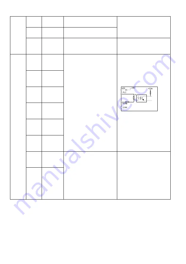
Opto-isolated input, please refer to the
introduction to the multifunctional
input/output terminal wiring
Input resistance: R=3.1k
Ω
;
maximum input frequency: 200Hz
Input voltage range: 20V~30V
X2
Multi-functional
input terminal
2
X3
Multi-functional
input terminal
3
X4
Multi-functional
input terminal
4
X5
Multi-functional
input terminal
5
X6
Multi-functional
input terminal
6
X7
Multi-functional
input terminal
7
In addition to acting as an ordinary
multi-functional terminals (same as
X1~X6), X7 and X8 can also be set as
the high-speed pulse input terminal. For
details, please refer to the introduction
to the functions of input terminals
P09.00~P09.07 in “Digital input/output
parameters” (Group P09) (common
terminal: PLC).
The equivalent diagram for the
opto-isolated input is shown as above,
please refer to the introduction to wiring
for the multi-functional input/output
terminals.
Input resistance: R=2k
Ω
Maximum input frequendy: 100kHz
Input voltage range: 20V~30V
X8
Multi-functional
input terminal
8
Содержание MV600L Series
Страница 57: ...57 1 0 0 4 P13 04 1 0 1 5 P13 05 1 1 0 6 P13 06 1 1 1 7 P13 07...
Страница 71: ...71 Appendix 2 Indentification of LED Display Symbols...
Страница 74: ...74...


