11
P
-DC
B1
B2
-10V~+10V
MV600L
PE
AI3-
AI3+
GND
AI1/ AI2
X
1
X2
X3
X4
X5
X6
X7
X8
-10
+10
COM
P24
PLC
R/L1
S/L2
T/L3
+DC
-DC
U
V
W
PE
12C
COM
PE
GND
AO1
Y
2
TB
TA
TC
BRA
BRC
M
PG
COM
RS485+
RS485-
AI1 AI2
0~10V
AO1 AO2
0~20mA
-10V~10V
0~20mA
AO2
B-
B+
A-
A+
P
PE
Y1
P24
DCL DC reactor
(External, default configuration)
Braking unit and resistor
(External, optional part)
Three-phase
380V
50/60Hz
Multi-function input 1
Multi-function input 2
Multi-function input 3
Multi-function input 4
Multi-function input 5
Multi-function input 6
Multi-function input 7
Multi-function input 8
Analog input
Analog differential input
Standard RS485
commmunication
port
Relay output 2
Relay output 1
Output 2
Open collector output
Frequency meter
(open collector output)
pulse signal output
4V
2
~
0
DC voltage/current meter
Voltage/current signal
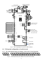
Fig. 2-2 Basic wiring diagram for products of 90kW and above
2.2 Wiring and configuration of control circuit
2.2.1 The arrangement sequence diagram of the control circuit terminals
Fig. 2-3 The arrangement sequence diagram of the control circuit terminals
Содержание MV600L Series
Страница 57: ...57 1 0 0 4 P13 04 1 0 1 5 P13 05 1 1 0 6 P13 06 1 1 1 7 P13 07...
Страница 71: ...71 Appendix 2 Indentification of LED Display Symbols...
Страница 74: ...74...


