background image


AVTMMIT30-EN  Rev E02 June 2009 

24 

INSPECTION AND 
MAINTENANCE PROCEDURE 

Proceed according to the steps below: 

1.


Visually inspect the unit case, noting that 
hinges and case locks function properly 

2.


Check for breaks and or cracks in the case or 
lid 

3.


Check that the cable bag remains firmly 
affixed to the lid 

4.


Remove the cables from the bag and set them 
aside. 

5.


Take note of the air transport valve; that it 
rotates smoothly and cinches down firmly. 

6.


Note the condition of the carry handle and 
case feet. 

7.


Wipe the exterior of the case with a damp 
cloth; then dry with a clean dry cloth. 
Detergents and special cleaning agents are 
neither required nor necessary. 

8.


Retrieve the cable set aside earlier, inspect the 
cables looking for damaged insulation or 
frayed jackets. Pay special attention to the HV 
output cable, check the condition of the 
crocodile clip, and ensure that the spring 
tension is sufficient and not damaged. The 

Содержание MIT30

Страница 1: ...alog No MIT30 High Voltage Equipment THIS EQUIPMENT PRODUCES INSTANTANEOUSLY LETHAL VOLTAGE Please read carefully before operating Safety is the responsibility of the user M Valley Forge Corporate Cen...

Страница 2: ......

Страница 3: ...30kV DC Insulation Tester MIT30 Catalog No MIT30 Instruction Manual...

Страница 4: ...cing or repairing at our option defective equipment Equipment returned to the factory for repair must be shipped prepaid and insured Contact your MEGGER representative for instructions and a return au...

Страница 5: ...11 Environmental 12 Regulatory Compliance 12 5 DESCRIPTION 13 6 SETTING UP 15 Selection of Location 15 Clearances 16 Connections Procedure 17 7 OPERATION 19 TEST PROCEDURE 19 USE OF GUARD 21 8 ROUTINE...

Страница 6: ...AVTMMIT30 EN Rev E02 June 2009 ii M...

Страница 7: ...In the normal course of testing a specimen or system is subjected to high DC voltage The resulting current and the manner in which the current varies with time provides data that indicates the conditi...

Страница 8: ...used in this manual is defined as a condition or practice which could result in personal injury or loss of life CAUTION Caution as used in this manual is defined as a condition or practice which coul...

Страница 9: ...test must stand clear of all parts of the complete high voltage circuit unless the test set is de energized and all parts of the test circuit are grounded Persons not directly associated with the work...

Страница 10: ...e test set kV meter reads zero all energized parts of the test setup MUST be short circuited by means of a safety grounding discharge rod or hot stick Ground bonds should then be applied to the equipm...

Страница 11: ...truction manual and do not use accessory items for any purpose except with the specified equipment Before operating read and follow the instruction manual Equipment operators must read this manual in...

Страница 12: ...M AVTMMIT30 EN Rev E02 June 2009 6 M...

Страница 13: ...8500 Fax 610 676 8625 Email VF Customer SVC Dept case sensitive no extension Web www megger com Examine the instrument for damage received in transit If any damage is discovered file a claim with the...

Страница 14: ...M AVTMMIT30 EN Rev E02 June 2009 8 M...

Страница 15: ...4 VAC 110 350 VDC Frequency DC 47 440 Hz Maximum 35 VA Fusing Double Pole 5 x 20mm ceramic 3 15A slow blow fuse 500 VAC Power Inlet C14 acc to IEC EN 60320 1 OUTPUT Voltage 0 to 30 kV Maximum Current...

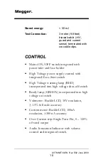
Страница 16: ...oltage power supply control with integrated Zero Start switch High Voltage warning lamp RED incorporated into high voltage shut off switch Ready lamp GREEN incorporated into high voltage on switch Vol...

Страница 17: ...High Voltage warning lamp High strength plastic case Cable interlock Air transport pressure relief valve PHYSICAL Length 360 mm 14 2 in Width 304 mm 12 in Depth 194 mm 7 6 in Weight 8 kg 17 6 lbs Impa...

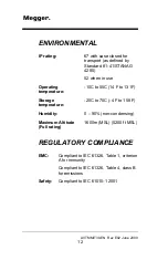
Страница 18: ...use Operating temperature 10C to 55C 14 F to 131F Storage temperature 20C to 70C 4 F to 158 F Humidity 0 90 non condensing Maximum Altitude Full rating 1600m MSL 5200 ft MSL REGULATORY COMPLIANCE EMC...

Страница 19: ...ltant current in the apparatus to which it is connected Designed for field use the test set is built into a durable rotary molded impact resistant case with carrying strap The test set consists of a v...

Страница 20: ...M AVTMMIT30 EN Rev E02 June 2009 14 M...

Страница 21: ...Working with due regard to safety identify the terminal of the apparatus to be tested Define the type of test required Setup barriers or use other means to keep unauthorized personnel away from all hi...

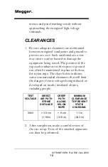
Страница 22: ...exposed conductors with respect to ground can often be maintained in place with clean dry nylon rope The chart below indicates some recommended clearances that will limit the danger of static voltages...

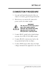
Страница 23: ...mains supply WARNING The third wire in the input power line is the system ground Operator and equipment safety depend on this connection being made to a good ground 3 Connect BLUE guard lead to drain...

Страница 24: ...M AVTMMIT30 EN Rev E02 June 2009 18 M...

Страница 25: ...ote Before operating the test set read Section 2 of this manual and ensure that all appropriate safety precautions are observed TEST PROCEDURE 1 Complete connection procedure as outlined in Section 6...

Страница 26: ...e the HV WARNING HIGH VOLTAGE PRESENT 8 When the RED button illuminates rotate the voltage control knob until the desired voltage is attained After Testing Is Completed 9 Rotate the voltage control to...

Страница 27: ...ypass any undesired currents see the following paragraphs regarding use of the guard terminal If the guard terminal is connected alone no current will be displayed If during the test the over current...

Страница 28: ...l in excluding the leakage of the surface path from the measurement This is easily accomplished by forming an electrode by wrapping a bare wire around the outer surface of the termination This wire el...

Страница 29: ...f damage Inspect meter faces for visible signs of damage Inspect output cable The cable should not show any radical changes in geometry Connectors should be free of distortion and burrs The outer jack...

Страница 30: ...Take note of the air transport valve that it rotates smoothly and cinches down firmly 6 Note the condition of the carry handle and case feet 7 Wipe the exterior of the case with a damp cloth then dry...

Страница 31: ...erviceable condition with no cracks Pay special attention to the HV voltage control knob with its locking feature Ensure that the lock engages and disengages smoothly CALIBRATION PROCEDURE REQUIRED EQ...

Страница 32: ...9 Turn the voltage control knob to 10 0 10 Adjust R38 on control PCB until 30 00 kV is read on the calibration voltmeter 11 Adjust R40 until the MIT30 voltmeter reads 30 00 12 Disengage high voltage 1...

Страница 33: ...0 A is displayed or the 30 kV limit is achieved 7 Read current measured through calibration ammeter 8 Read current measured by on board ammeter 9 If the difference between the calibration ammeter and...

Страница 34: ...M AVTMMIT30 EN Rev E02 June 2009 28 M...

Страница 35: ...oltage DC power supply capable of sourcing 330 A Output voltage and current is displayed on high contrast liquid crystal displays The MIT30 has an active over current trip that can be adjusted between...

Страница 36: ...tripped a relay on the control board enables the high voltage power supply and opens the discharge switch If the cable interlock or the over current sensor is activated during operation the high volt...

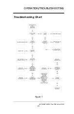
Страница 37: ...OPERATION TROUBLESHOOTING AVTMMIT30 EN Rev E02 June 2009 31 Troubleshooting Chart Figure 1...

Страница 38: ...M AVTMMIT30 EN Rev E02 June 2009 32 M...

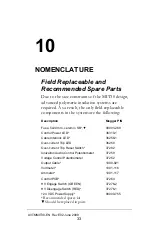
Страница 39: ...Description Megger P N Fuse 5x20 mm ceramic SB 90001 269 Control Power LED 36310 1 Cable Interlock LED 36258 1 Over current Trip LED 36258 Over current Trip Reset Switch 37282 Ionization Audio Control...

Страница 40: ...M AVTMMIT30 EN Rev E02 June 2009 34 Figure 2...

Страница 41: ...NOMENCLATURE AVTMMIT30 EN Rev E02 June 2009 35 This page intentionally left blank...

Страница 42: ...k LED RED 1 4 36258 Over current Trip LED RED 1 5 37282 Over current Trip Reset Switch 1 6 37259 Ionization Audio Control Potentiometer 1 7 37252 Voltage Control Potentiometer 1 8 1000 921 Output Cabl...

Страница 43: ...NOMENCLATURE AVTMMIT30 EN Rev E02 June 2009 37 Figure 4...

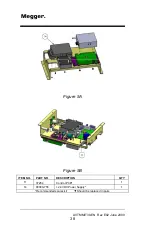
Страница 44: ...M AVTMMIT30 EN Rev E02 June 2009 38 Figure 5A Figure 5B ITEM NO PART NO DESCRIPTION QTY 11 37264 Control PCB 1 14 90000 755 24 VDC Power Supply 1 Recommended spares kit Should be replaced in pairs...

Отзывы: